12 August 2016

5.3 iSCSI Architecture and Addressing

SCSI is the command protocol that works at the application layer of the Open System Interconnection (OSI) model. The initiators and the targets use SCSI commands and responses to talk to each other. The SCSI commands, data, and status messages are encapsulated into TCP/IP and transmitted across the network between the initiators and the targets.

iSCSI Architecture

The below figure displays a model of iSCSI protocol layers and depicts the encapsulation order of the SCSI commands for their delivery through a physical carrier.


iSCSI SAN Architecture

iSCSI is the session-layer protocol that initiates a reliable session between devices that recognize SCSI commands and TCP/IP. The iSCSI session-layer interface is responsible for handling login, authentication, target discovery, and session management.

TCP is used with iSCSI at the transport layer to provide reliable transmission. TCP controls message flow, windowing, error recovery, and retransmission. It relies upon the network layer of the OSI model to provide global addressing and connectivity. The OSI Layer 2 protocols at the data link layer of this model enable node-to-node communication through a physical network.

iSCSI Addressing

Both the initiators and the targets in an iSCSI environment have iSCSI addresses that facilitate communication between them. An iSCSI address is comprised of the location of an iSCSI initiator or target on the network and the iSCSI name. The location is a combination of the host name or IP address and the TCP port number. 

For iSCSI initiators, the TCP port number is omitted from the address. iSCSI name is a unique worldwide iSCSI identifier that is used to identify the initiators and targets within an iSCSI network to facilitate communication. The unique identifier can be a combination of the names of the department, application, manufacturer, serial number, asset number, or any tag that can be used to recognize and manage the iSCSI nodes. The following are three types of iSCSI names commonly used.

iSCSI Addressing

iSCSI Qualified Name (IQN): An organization must own a registered domain name to generate iSCSI Qualified Names. This domain name does not need to be active or resolve to an address. It just needs to be reserved to prevent other organizations from using the same domain name to generate iSCSI names. A date is included in the name to avoid potential conflicts caused by the transfer of domain names. An example of an IQN is iqn.2015-04.com.example:optional_string. The optional_string provides a serial number, an asset number, or any other device identifiers. IQN enables storage administrators to assign meaningful names to the iSCSI initiators and the iSCSI targets, and therefore, manages those devices more easily.

Extended Unique Identifier (EUI): An EUI is a globally unique identifier based on the IEEE EUI-64 naming standard. An EUI is composed of the eui prefix followed by a 16-character hexadecimal name, such as eui.0300732A32598D26.

Network Address Authority (NAA): NAA is another worldwide unique naming format as defined by the InterNational Committee for Information Technology Standards (INCITS) T11 - Fibre Channel (FC) protocols and is used by Serial Attached SCSI (SAS). This format enables the SCSI storage devices that contain both iSCSI ports and SAS ports to use the same NAA-based SCSI device name. An NAA is composed of the naa prefix followed by a hexadecimal name, such as naa.52004567BA64678D. The hexadecimal representation has a maximum size of 32 characters (128 bit identifier).

iSCSI Discovery

An iSCSI initiator must discover the location of its targets on the network and the names of the targets available to it before it can establish a session. This discovery commonly takes place in two ways: SendTargets discovery or internet Storage Name Service (iSNS).

SendTargets discovery: In SendTargets discovery, the initiator is manually configured with the target’s network portal (IP address and TCP port number) to establish a discovery session. The initiator issues the SendTargets command, and thereby the target network portal responds to the initiator with the location and name of the target.

iSNS: iSNS in the iSCSI SAN is equivalent in function to the Name Server in an FC SAN. It enables automatic discovery of iSCSI devices on an IP-based network. The initiators and targets can be configured to automatically register themselves with the iSNS server. Whenever an initiator wants to know the targets that it can access, it can query the iSNS server for a list of available targets.

11 August 2016

5.2 iSCSI Interfaces and Connectivity types

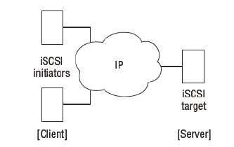
iSCSI SANs are composed of initiators and targets connected by an IP network where server acts as the initiator or ISCSI host and the iSCSI storage device acts as the target or ISCSI array. These iSCSI initiators and targets require a physical interface to the network to transfer the data. 

These interfaces are usually PCI devices that are either integrated to the server motherboard or included as PCI expansion cards. They connect to the intermediate TCP/IP network via copper or fiber-optic cables.  Based on the performance and cost, there are different types of iSCSI initiator which can be used to deploy iSCSI SAN.

Types of iSCSI initiators

A standard NIC with software iSCSI adapter, a TCP offload engine (TOE) NIC with software iSCSI adapter,  iSCSI HBA and Converged Network Adapter (CNA) are the four common types of iSCSI initiators

Standard NIC with software iSCSI adapter: The software iSCSI adapter is an operating system (OS) or hypervisor kernel-resident software that uses an existing NIC of the compute system to emulate an iSCSI initiator. It is least expensive and easy to implement because most compute systems come with at least one, and in many cases two embedded NICs. It requires only a software initiator for iSCSI functionality. Because NICs provide standard networking function, both the TCP/IP processing and the encapsulation of SCSI data into IP packets are carried out by the CPU of the server or host. This places additional overhead on the CPU. If a standard NIC is used in heavy I/O load situations, the CPU of the server might become a bottleneck.

TOE NIC with software iSCSI adapter: A TOE NIC offloads the TCP/IP processing from the CPU of a host and leaves only the iSCSI functionality to the CPU. The host passes the iSCSI information to the TOE NIC and then the TOE NIC sends the information to the destination using TCP/IP. Although this solution improves performance, the iSCSI functionality is still handled by a software adapter that requires CPU cycles of the compute system.

iSCSI HBA: An iSCSI HBA is a hardware adapter with built-in iSCSI functionality. It is capable of providing performance benefits over software iSCSI adapters by offloading the entire iSCSI and TCP/IP processing from the CPU of a compute system. This offloads all the TCP and iSCSI processing from the host CPU to the processor on the host bus adapter (HBA). They also have optional ROM which allows disk-less servers to be booted from the iSCSI SAN.

Converged Network Adapter: It offers everything that iSCSI HBA offers such as reduced pressure on host CPU and booting options but has the added versatility of being dynamically configurable for protocols other than iSCSI such as FCoE. This is more discussed in FCOE chapter.

Standard NIC is the most commonly used and simple to setup in test environment but you could not depend on it in real time critical applications. Deciding which of these is best for your environment may be depend upon the requirements such as cost and performance factors. However, all of these options appear to the OS as SCSI adapters, therefore the OS is unable to distinguish volumes presented through the iSCSI SAN from volumes on a local disk inside the server. This makes using iSCSI SAN with existing systems simple and easy.

iSCSI Connectivity types

The iSCSI implementations support two types of connectivity

  • Native iSCSI
  • Bridged iSCSI
Native iSCSI: In this type of connectivity, the host with iSCSI initiators may be either directly attached to the iSCSI targets (iSCSI-capable storage systems) or connected through an IP-based network. FC components are not required for native iSCSI connectivity. Below figure shows a native iSCSI implementation that includes a storage system with an iSCSI port. The storage system is connected to an IP network. After an iSCSI initiator is logged on to the network, it can access the available LUNs on the storage system.

iscsi SAN connectivity

Bridged iSCSI: This type of connectivity allows the initiators to exist in an IP environment while the storage systems remain in an FC SAN environment. It enables the coexistence of FC with IP by providing iSCSI-to-FC bridging functionality. The above figure illustrates a bridged iSCSI implementation. It shows connectivity between a compute system with an iSCSI initiator and a storage system with an FC port. 

As the storage system does not have any iSCSI port, a gateway or a multiprotocol router is used. The gateway facilitates the communication between the compute system with iSCSI ports and the storage system with only FC ports. The gateway converts IP packets to FC frames and vice versa, thereby bridging the connectivity between the IP and FC environments. The gateway contains both FC and Ethernet ports to facilitate the communication between the FC and the IP environments. The iSCSI initiator is configured with the gateway’s IP address as its target destination. On the other side, the gateway is configured as an FC initiator to the storage system.

Previous: 5.1 Introduction to IP SAN and their components

10 August 2016

5.1 Introduction to IP SAN and their components

As discussed in previous chapter Fibre Channel (FC) SAN provides high performance and scalability. These advantages of FC SAN come with the burden of additional cost of buying FC components, such as FC HBA and FC switches. So to overcome these cost burden, we have another type of Storage Area networks called IP SAN.

IP SAN uses Internet Protocol (IP) for the transport of storage traffic instead of Fibre Channel (FC) cables. It transports block I/O over an IP-based network. Two primary protocols that leverage IP as the transport mechanism for block-level data transmission are 
  • Internet SCSI (iSCSI)
  • Fibre Channel over IP (FCIP).
iSCSI is a storage networking technology which allows storage resources to be shared over an IP network Whereas FCIP is an IP-based protocol that enables distributed FC SAN islands to be interconnected over an existing IP network. In FCIP, FC frames are encapsulated onto the IP payload and transported over an IP network.

IP is a matured technology and using IP as a storage networking option provides several advantages. 
  • Most organizations have an existing IP-based network infrastructure, which could also be used for storage networking and may be a more economical option than deploying a new FC SAN infrastructure.
  • IP network has no distance limitation, which makes it possible to extend or connect SANs over long distances. With IP SAN, organizations can extend the geographical reach of their storage infrastructure and transfer data that are distributed over wide locations.
  • Many long-distance disaster recovery (DR) solutions are already leveraging IP-based networks. In addition, many robust and mature security options are available for IP networks.
Typically, a storage system comes with both FC and iSCSI ports. This enables both the native iSCSI connectivity and the FC connectivity in the same environment.

Lets look at how iSCSI based SAN works and FC based IP SAN works in this chapter


iSCSI SAN Overview

As said earlier, iSCSI is a storage networking technology which allows storage resources to be shared over an IP network and most of the storage resources which are shared on an iSCSI SAN are disk resources. Just like as SCSI messages are mapped on Fibre Channel in FC SAN, iSCSI is a mapping of SCSI protocol over TCP/IP. 

iSCSI is an acronym for Internet Small Computer System Interface, it deals with block storage and maps SCSI over traditional TCP/IP. This protocol is mostly used for sharing primary storage such as disk drives and in some cases it is used for disk backup environment aswell.

SCSI commands are encapsulated at each layer of the network stack for eventual transmission over an IP network. The TCP layer takes care of transmission reliability and in-order delivery whereas the IP layer provides routing across the network.


iSCSI SAN
In iSCSI SAN, initiators issue read/write data requests to targets over an IP network. Targets respond to initiators over the same IP network. All iSCSI communications follow this request response mechanism and all requests and responses are passed over the IP network as iSCSI Protocol Data Units (PDUs). iSCSI PDU is the fundamental unit of communication in an iSCSI SAN.


iSCSI performance is influenced by three main components. Best initiator performance can be achieved with dedicated iSCSI HBAs, target performance can be achieved by purpose-built iSCSI arrays and finally the network performance can be achieved by dedicated network switches

Multiple layers of security should be implemented on an iSCSI SAN as security is the most important in IT infra. These include CHAP for authentication, discovery domains to restrict device discovery, network isolation and IPsec for encryption of in-flight data.

iSCSI components

iSCSI is an IP-based protocol that establishes and manages connections between hosts and storage systems over IP. iSCSI is an encapsulation of SCSI I/O over IP. 

iSCSI encapsulates SCSI commands and data into IP packets and transports them using TCP/IP. iSCSI is widely adopted for transferring SCSI data over IP between hosts and storage systems and among the storage systems. It is relatively inexpensive and easy to implement, especially environments in which an FC SAN does not exist.
iscsi san components
Key components for iSCSI communication are
  • iSCSI initiators such as an iSCSI HBA
  • iSCSI targets such as a storage system with an iSCSI port
  • IP-based network such as a Gigabit Ethernet LAN An iSCSI initiator sends commands and associated data to a target and the target returns data and responses to the initiator.
Previous: 4.8 Basic troubleshooting tips for Fibre Channel (FC) SAN

8 August 2016

4.8 Basic troubleshooting tips for Fibre Channel (FC) SAN issues

There are many areas where the errors can be made and you might experience lots of issues with the mis-configuration settings. A thorough and deep understanding of the SAN configuration is needed to troubleshoot any storage related issues. Slight differences can make a huge data loss and could make the organisation collapse. To troubleshoot any kind of situation, follow these tips as a starting step before the advanced troubleshooting. There might be other tools to troubleshoot the issues but these are basic first steps which might help you save the time.

1) Always take backup of Switch Configurations

Regular backup of switch configurations needs to be done just in regular intervals just in case if you are unable to troubleshoot the issue and needs to revert back to the previous configuration. Such backup files tend to be human-readable flat files that are extremely useful if you need to compare a broken configuration image to a previously known working configuration. Another option might be to create a new zone configuration each time you make a change, and maintain previous versions that can be rolled back to if there are problems after committing the change.

2) Troubleshooting Connectivity Issues

Many of the day-to-day issues that you see are connectivity issues such as hosts not being able to see a new LUN or not being able to see storage or tape devices on the SAN. Connectivity issues will be due to misconfigured zoning. Each vendor provides different tools to configure and troubleshoot zoning, but the following common CLI commands can prove very helpful.

fcping
fcping is an FC version of the popular IP ping tool. fcping allows you to test the following:
  • Whether a device (N_Port) is alive and responding to FC frames
  • End-to-end connectivity between two N_Ports
  • Latency
  • Zoning between two devices
fcping is available on most switch platforms as well as being a CLI tool for most operating systems and some HBAs. It works by sending Extended Link Service (ELS) echo request frames to a destination, and the destination responding with ELS echo response frames. For example

# fcping 50:01:43:80:05:6c:22:ae

fctrace
Another tool that is modeled on a popular IP networking tool is the fctrace tool. This tool traces a route/path to an N_Port. The following command shows an fctrace command example

# fctrace fcid 0xef0010 vsan 1

3) Things to check while troubleshooting Zoning
  • Are your aliases correct ?
  • If using port zoning, have your switch domain IDs changed ?
  • If using WWPN zoning, have any of the HBA/WWPNs been changed ?
  • Is your zone in the active zone set?

4) Rescan the SCSI Bus if required

After making zoning changes, LUN masking changes or any other work that changes a LUN/volume presentation to a host, you may be required to rescan the SCSI bus on that host in order to detect the new device. The following command shows how to rescan the SCSI bus on a Windows server using the diskpart tool

DISKPART> list disk

DISKPART> rescan

If you know that your LUN masking and zoning are correct but the server still does not see the device, it may be necessary to reboot the host.

5) Understanding Switch Configuration Dumps

Each switch vendor also tends to have a built-in command/script that is used to gather configs and logs to be sent to the vendor for their tech support groups to analyze. The output of these commands/scripts can also be useful to you as a storage administrator. Each vendor has its own version of these commands/scripts

Cisco      -      show tech-support
Brocade  -     supportshow or supportsave
QLogic    -     create support

6) Use Port Error Counters

Switch-based port error counters are an excellent way to identify physical connectivity issues such as
  • Bad cables (bent, kinked, or otherwise damaged cables)
  • Bad connectors (dust on the connectors, loose connectors)
The following example shows the error counters for a physical switch port on a  switch:

admin> portshow 4/15

These port counters can sometimes be misleading. It is perfectly normal to see high counts
against some of the values, and it is common to see values increase when a server is rebooted and when similar changes occur. If you are not sure what to look for, check your switch documentation, but also compare the counters to some of your known good ports.

If some counters are increasing on a given port that you are concerned with, but they are not increasing on some known good ports, then you know that you have a problem on that port.

Other commands show similar error counters as well as port throughput. The following porterrshow command shows some encoding out (enc out) and class 3 discard (disc c3) errors on port 0. This may indicate a bad cable, a bad port, or another hardware problem

admin> porterrshow


                                                                 Next: 5.1 Introduction to IP SAN and their components

4.7 Introduction to VSAN

Virtualizing FC SAN (VSAN)

Virtual SAN (also called virtual fabric) is a logical fabric on an FC SAN, which enables communication among a group of nodes regardless of their physical location in the fabric.

Each SAN can be partitioned into smaller virtual fabrics, generally called as VSANs. VSANs are similar to VLANs in the networking and allows to partition physical kit into multiple smaller logical SANs/fabrics. It is possible to route traffic between virtual fabrics by using vendor-specific technologies. 

In a VSAN, a group of node ports communicate with each other using a virtual topology defined on the physical SAN. Multiple VSANs may be created on a single physical SAN. Each VSAN behaves and is managed as an independent fabric. Each VSAN has its own fabric services, configuration, and set of FC addresses. Fabric-related configurations in one VSAN do not affect the traffic in another VSAN. A VSAN may be extended across sites, enabling communication among a group of nodes, in either site with a common set of requirements.

VSAN

VSANs improve SAN security, scalability, availability, and manageability. VSANs provide enhanced security by isolating the sensitive data in a VSAN and by restricting the access to the resources located within that VSAN. 

For example, a cloud provider typically isolates the storage pools for multiple cloud services by creating multiple VSANs on an FC SAN. Further, the same FC address can be assigned to nodes in different VSANs, thus increasing the fabric scalability. 

The events causing traffic disruptions in one VSAN are contained within that VSAN and are not propagated to other VSANs. VSANs facilitate an easy, flexible, and less expensive way to manage networks. Configuring VSANs is easier and quicker compared to building separate physical FC SANs for various node groups. To regroup nodes, an administrator simply changes the VSAN configurations without moving nodes and recabling.

Configuring VSAN

To configure VSANs on a fabric, an administrator first needs to define VSANs on fabric switches. Each VSAN is identified with a specific number called VSAN ID. The next step is to assign a VSAN ID to the F_Ports on the switch. By assigning a VSAN ID to an F_Port, the port is included in the VSAN. In this manner, multiple F_Ports can be grouped into a VSAN. 

For example, an administrator may group switch ports (F_Ports) 1 and 2 into VSAN 10 (ID) and ports 6 to 12 into VSAN 20 (ID). If an N_Port connects to an F_Port that belongs to a VSAN, it becomes a member of that VSAN. The switch transfers FC frames between switch ports that belong to the same VSAN.

VSAN versus Zone

Both VSANs and zones enable node ports within a fabric to be logically segmented into groups. But they are not same and their purposes are different. There is a hierarchical relationship between them. An administrator first assigns physical ports to VSANs and then configures independent zones for each VSAN. A VSAN has its own independent fabric services, but the fabric services are not available on a per-zone basis.

VSAN Trunking

VSAN trunking allows network traffic from multiple VSANs to traverse a single ISL. It supports a single ISL to permit traffic from multiple VSANs along the same path. The ISL through which multiple VSAN traffic travels is called a trunk link. 

VSAN trunking enables a single E_Port to be used for sending or receiving traffic from multiple VSANs over a trunk link. The E_Port capable of transferring multiple VSAN traffic is called a trunk port. The sending and receiving switches must have at least one trunk E_Port configured for all of or a subset of the VSANs defined on the switches. 

VSAN trunking eliminates the need to create dedicated ISL(s) for each VSAN. It reduces the number of ISLs when the switches are configured with multiple VSANs. As the number of ISLs between the switches decreases, the number of E_Ports used for the ISLs also reduces. By eliminating needless ISLs, the utilization of the remaining ISLs increases. The complexity of managing the FC SAN is also minimized with a reduced number of ISLs.

VSAN Tagging

VSAN tagging is the process of adding or removing a marker or tag to the FC frames that contains VSAN-specific information. Associated with VSAN trunking, it helps isolate FC frames from multiple VSANs that travel through and share a trunk link. Whenever an FC frame enters an FC switch, it is tagged with a VSAN header indicating the VSAN ID of the switch port (F_Port) before sending the frame down to a trunk link. 


The receiving FC switch reads the tag and forwards the frame to the destination port that corresponds to that VSAN ID. The tag is removed once the frame leaves a trunk link to reach an N_Port.

Previous: 4.6 Fibre Channel (FC) SAN Topologies

                                                                                              Next: 4.8 Basic troubleshooting tips for Fibre Channel (FC) SAN

4.6 Fibre Channel (FC) SAN Topologies Overview

Out of the FC SAN inter-connectors such as Hub, Switch and Directors, FC Switch and FC Directors are majorly used devices in any Storage Area Network. These FC switches and FC directors may be connected in a number of ways to form different fabric topologies. Each topology provides certain benefits.


Fibre Channel (FC) SAN Topologies

FC SAN offers 3 types of FC Switch topologies.  They are

Single-Switch Topology

In a single-switch topology, the fabric consists of only a single switch. Both the compute systems and the storage systems are connected to the same switch. A key advantage of a single-switch fabric is that it does not need to use any switch port for ISLs. Therefore, every switch port is usable for compute system or storage system connectivity. Further, this topology helps eliminate FC frames travelling over the ISLs and consequently eliminates the ISL delays.

Single FC Switch Topology

A typical implementation of a single-switch fabric would involve the deployment of an FC director. FC directors are high-end switches with a high port count. When additional switch ports are needed over time, new ports can be added via add-on line cards (blades) in spare slots available on the director chassis. To some extent, a bladed solution alleviates the port count scalability problem inherent in a single-switch topology.

Mesh Topology

A mesh topology may be one of the two types: full mesh or partial mesh. In a full mesh, every switch is connected to every other switch in the topology. A full mesh topology may be appropriate when the number of switches involved is small. A typical deployment would involve up to four switches or directors, with each of them servicing highly localised compute-to-storage traffic. In a full mesh topology, a maximum of one ISL or hop is required for compute-to-storage traffic. However, with the increase in the number of switches, the number of switch ports used for ISL also increases. This reduces the available switch ports for node connectivity.

Mesh Topology

In a partial mesh topology, not all the switches are connected to every other switch. In this topology, several hops or ISLs may be required for the traffic to reach its destination. Partial mesh offers more scalability than full mesh topology. However, without proper placement of compute and storage systems, traffic management in a partial mesh fabric might be complicated and ISLs could become overloaded due to excessive traffic aggregation.

Core-edge Topology

The core-edge topology has two types of switch tiers: edge and core.

The edge tier is usually composed of switches and offers an inexpensive approach to adding more compute systems in a fabric. The edge-tier switches are not connected to each other. Each switch at the edge tier is attached to a switch at the core tier through ISLs.

The core tier is usually composed of directors that ensure high fabric availability. In addition, typically all traffic must either traverse this tier or terminate at this tier. In this configuration, all storage systems are connected to the core tier, enabling compute-to-storage traffic to traverse only one ISL. Compute systems that require high performance may be connected directly to the core tier and consequently avoid ISL delays.

Core-edge Toplogy

The core-edge topology increases connectivity within the FC SAN while conserving the overall port utilization. It eliminates the need to connect edge switches to other edge switches over ISLs. Reduction of ISLs can greatly increase the number of node ports that can be connected to the fabric. If fabric expansion is required, then administrators would need to connect additional edge switches to the core. The core of the fabric is also extended by adding more switches or directors at the core tier. Based on the number of core-tier switches, this topology has different variations, such as single-core topology and dual-core topology. To transform a single-core topology to dual-core, new ISLs are created to connect each edge switch to the new core switch in the fabric.

Link Aggregation

Link aggregation combines two or more parallel ISLs into a single logical ISL, called a port-channel, yielding higher throughput than a single ISL could provide. For example, the aggregation of 10 ISLs into a single port-channel provides up to 160 Gb/s throughput assuming the bandwidth of an ISL is 16 Gb/s. 

Link Aggregation

Link aggregation optimizes fabric performance by distributing network traffic across the shared bandwidth of all the ISLs in a port-channel. This allows the network traffic for a pair of node ports to flow through all the available ISLs in the port-channel rather than restricting the traffic to a specific, potentially congested ISL. The number of ISLs in a port channel can be scaled depending on application’s performance requirement.

Previous: 4.5 Fibre Channel (FC) Zoning Overview

                                                                                                 Next: 4.7  Introduction to VSAN

4.5 Fibre Channel (FC) Zoning Overview

In general the initiator performs the discovery of all the devices in a SAN environment. If zoning is not done previously, the initiator will probe and discover all devices on the SAN fabric. As part of the discovery , every device will also be queried to discover its properties and capabilities. On a large this could take forever and be a massive waste of time and resources. So inorder to speed up and smooth this discovery process, the  name server was created. Each time any device joins the fabric, it performs a process referred as a fabric login (FLOGI). This FLOGI assigns a 24 bit N-Port IDS to all the devices and specifies the class of service to be used.


After a successful FLOGI process, the device then performs a port login (PLOGI) to the name server to register its capabilities. All devices joining a fabric perform PLOGI to the name server. As part of the PLOGI, the device will ask the name server for a list of devices on the fabric and this is where zoning is helpful. Instead of returning a list of all devices on the fabric, the name server returns only a list of those devices that are zoned so as to accessible from the device performing the PLOGI. This process is quicker and more secure that probing the entire SAN for all the devices and it is also allows for greater control and more flexible SAN management.  

Whenever a change takes place in the name server database, the fabric controller sends a Registered State Change Notification (RSCN) to all the nodes impacted by the change. If zoning is not configured, the fabric controller sends the RSCN to all the nodes in the fabric.

Involving the nodes that are not impacted by the change increases the amount of fabric-management traffic. For a large fabric, the amount of FC traffic generated due to this process can be significant and might impact the compute-to-storage data traffic. Zoning helps to limit the number of RSCNs in a fabric. In the presence of zoning, a fabric sends the RSCN to only those nodes in a zone where the change has occurred.

What is Zoning ?

Zoning is an FC switch function that enables node ports within the fabric to be logically segmented into groups and communicate with each other within the group.

FC Zoning

Zoning also provides access control, along with other access control mechanisms, such as LUN masking. Zoning provides control by allowing only the members in the same zone to establish communication with each other. Multiple zones can be grouped together to form a zone set and this zone set is applied to the fabric. Any new zone configured needs to be added to the active zone set in order to applied to the fabric.

Zone members, zones, and zone sets form the hierarchy defined in the zoning process. A zone set is composed of a group of zones that can be activated or deactivated as a single entity in a fabric. Multiple zone sets may be defined in a fabric, but only one zone set can be active at a time. Members are the nodes within the FC SAN that can be included in a zone.

FC switch ports, FC HBA ports, and storage system ports can be members of a zone. A port or node can be a member of multiple zones. Nodes distributed across multiple switches in a switched fabric may also be grouped into the same zone. Zone sets are also referred to as zone configurations.

Best Practices for Zoning
  • Always keep the zones small so that the troubleshooting may get simpler.
  • Have only a single initiator in each zone and it is not recommended to have more than one initiator in a zone.
  • To make troubleshooting easier, also keep the number of targets in a zone small.
  • Give meaningful aliases and names to your zones so that they can easily identified during troubleshooting.
  • Zone changes need to be done with extreme caution and caring to prevent unwanted access of sensitive data.

Zoning can be categorized into three types:

WWN zoning: It uses World Wide Names to define zones. The zone members are the unique WWN addresses of the FC HBA and its targets (storage systems). A major advantage of WWN zoning is its flexibility. If an administrator moves a node to another switch port in the fabric, the node maintains connectivity to its zone partners without having to modify the zone configuration. This is possible because the WWN is static to the node port. WWN zoning is also referred as soft zoning sometimes.

FC SAN Zoning

Port zoning: It uses the switch port ID to define zones. In port zoning, access to node is determined by the physical switch port to which a node is connected. The zone members are the port identifiers (switch domain ID and port number) to which FC HBA and its targets (storage systems) are connected. If a node is moved to another switch port in the fabric, port zoning must be modified to allow the node, in its new port, to participate in its original zone. However, if an FC HBA or storage system port fails, an administrator just has to replace the failed device without changing the zoning configuration. Port zoning is also referred as hard zoning sometimes.

Mixed zoning: It combines the qualities of both WWN zoning and port zoning. Using mixed zoning enables a specific node port to be tied to the WWN of another node.

Previous: Introduction to Fibre Channel (FC) SAN Architecture and port virtualization 

                                                                                                                        Next: Fibre Channel (FC) SAN Topologies

4.4 Introduction to Fibre Channel (FC) SAN Architecture and port virtualization

The FC SAN physical components such as network cables network adapters and hubs or switches can be used to design a Fibre channel Storage Area Network.The different types of FC architecture which can be designed are
  • Point-to-point
  • Fibre channel arbitrated loop (FC-AL)
  • Fibre channel switched fabric (FC-SW). 

Fibre Channel (FC) SAN Architectures

The configuration of the above 3 architectures are explained below

Point-to-point Architecture:  In this configuration, two nodes are connected directly to each other. This configuration provides a dedicated connection for data transmission between nodes. However, the point-to-point configuration offers limited connectivity and scalability and is used in a DAS environment.
Point-to-Point FC


FC-Arbitrated Loop: In this configuration, the devices are attached to a shared loop. Each device contends with other devices to perform I/O operations. The devices on the loop must “arbitrate” to gain control of the loop. At any given time, only one device can perform I/O operations on the loop. Because each device in a loop must wait for its turn to process an I/O request, the overall performance in FC-AL environments is low. 

FC Arbirated Loop

Further, adding or removing a device results in loop re-initialization, which can cause a momentary pause in loop traffic. As a loop configuration, FC-AL can be implemented without any interconnecting devices by directly connecting one device to another two devices in a ring through cables. However, FC-AL implementations may also use FC hubs through which the arbitrated loop is physically connected in a star topology.

FC-Switch: It involves a single FC switch or a network of FC switches (including FC directors) to interconnect the nodes. It is also referred to as fabric connect. A fabric is a logical space in which all nodes communicate with one another in a network. In a fabric, the link between any two switches is called an interswitch link (ISL). ISLs enable switches to be connected together to form a single, larger fabric. 

FC Switch

They enable the transfer of both storage traffic and fabric management traffic from one switch to another. In FC-SW, nodes do not share a loop; instead, data is transferred through a dedicated path between the nodes. Unlike a loop configuration, an FC-SW configuration provides high scalability. The addition or removal of a node in a switched fabric is minimally disruptive; it does not affect the ongoing traffic between other nodes.

FC switches operate up to FC-2 layer, and each switch supports and assists in providing a rich set of fabric services such as the FC name server, the zoning database and time synchronization service. When a fabric contains more than one switch, these switches are connected through a link known as an inter-switch link.

Inter-switch links (ISLs) connect multiple switches together, allowing them to merge into a common fabric that can be managed from any switch in the fabric. ISLs can also be bonded into logical ISLs that provide the aggregate bandwidth of each component ISL as well as providing load balancing and high-availability features.

Fibre Channel (FC) Port Types

The ports in a switched fabric can be one of the following types
  • N_Port: It is an end point in the fabric. This port is also known as the node port. Typically, it is a compute system port (FC HBA port) or a storage system port that is connected to a switch in a switched fabric.
  • E_Port: It is a port that forms the connection between two FC switches. This port is also known as the expansion port. The E_Port on an FC switch connects to the E_Port of another FC switch in the fabric ISLs.
  • F_Port: It is a port on a switch that connects an N_Port. It is also known as a fabric port.
  • G_Port: It is a generic port on a switch that can operate as an E_Port or an F_Port and determines its functionality automatically during initialization.
FC Ports
Common FC ports speeds are 2 Gbps, 4Gbps, 8Gbps and 16Gbps. FC ports along with HBA ports, switch ports and storage array ports can be configured to autonegotiate their speed, autonegotiate is a protocol that allows two devices to agree on a common speed for the link. It is a good practice to hard-code the same speed at both ends of the link.

World Wide Name (WWN)

Each device in the FC environment is assigned a 64-bit unique identifier called the World Wide Name (WWN). The FC environment uses two types of WWNs.

wwwn
  • World Wide Node Name (WWNN) - WWNN is used to physically identify FC network adapters. Unlike an FC address, which is assigned dynamically, a WWN is a static name for each device on an FC network. WWNs are similar to the Media Access Control (MAC) addresses used in IP networking. 
  • WWNs are burned into the hardware or assigned through software. Several configuration definitions in an FC SAN use WWN for identifying storage systems and FC HBAs. WWNs are critical for FC SAN configuration as each node port has to be registered by its WWN before the FC SAN recognizes it.
  • World Wide Port Name (WWPN) - WWPN is used to physically identify FC adapter ports or node ports. For example, a dual-port FC HBA has one WWNN and two WWPNs.

N_Port Virtualization

The proliferation of compute systems in a data centre causes increased use of edge switches in a fabric. As the edge switch population grows, the number of domain IDs may become a concern because of the limitation on the number of domain IDs in a fabric. N_Port.

Virtualization (NPV) addresses this concern by reducing the number of domain IDs in a fabric. Edge switches supporting NPV do not require a domain ID. They pass traffic between the core switch and the compute systems. NPV-enabled edge switches do not perform any fabric services, and instead forward all fabric activity, such as login and name server registration to the core switch.

All ports at the NPV edge switches that connect to the core switch are established as NP_Ports (not E_Ports). The NP_Ports connect to an NPIV-enabled core director or switch. If the core director or switch is not NPIV-capable, the NPV edge switches do not function. As the switch enters or exits from NPV mode, the switch configuration is erased and it reboots. Therefore, administrators should take care when enabling or disabling NPV on a switch. The figure on the slide shows a core-edge fabric that comprises two edge switches in NPV mode and one core switch (an FC director).

N_Port ID virtualization (NPIV) 

It enables a single N_Port (such as an FC HBA port) to function as multiple virtual N_Ports. Each virtual N_Port has a unique WWPN identity in the FC SAN. This allows a single physical N_Port to obtain multiple FC addresses. 

NPIV
VMware or Hypervisors leverage NPIV to create virtual N_Ports on the FC HBA and then assign the virtual N_Ports to virtual machines (VMs). A virtual N_Port acts as a virtual FC HBA port. This enables a VM to directly access LUNs assigned to it 

NPIV enables an administrator to restrict access to specific LUNs to specific VMs using security techniques like zoning and LUN masking; similarly to the assignment of a LUN to a physical compute system. To enable NPIV, both the FC HBAs and the FC switches must support NPIV. The physical FC HBAs on the compute system, using their own WWNs, must have access to all LUNs that are to be accessed by VMs running on that compute system.

Previous: 4.3 Overview of Fibre Channel (FC) SAN Protocol

                                                                                                               Next: 4.5 Fibre Channel (FC) Zoning Overview