Traditionally, compute operating systems have communicated with peripheral devices over channel connections, such as Enterprise Systems Connection (ESCON) and SCSI. Channel technologies provide high levels of performance with low protocol overheads. Such performance is achievable due to the static nature of channels and the high level of hardware and software integration provided by the channel technologies. However, these technologies suffer from inherent limitations in terms of the number of devices that can be connected and the distance between these devices.
In contrast to channel technology, network technologies are more flexible and provide greater distance capabilities. Network connectivity provides greater scalability and uses shared bandwidth for communication. This flexibility results in greater protocol overhead and reduced performance.
Also Read: Introduction to VSAN
Also Read: Introduction to VSAN
The FC architecture represents true channel and network integration and captures some of the benefits of both channel and network technology. FC protocol provides both the channel speed for data transfer with low protocol overhead and the scalability of network technology. FC provides a serial data transfer interface that operates over copper wire and optical fiber.
Introduction to Fibre Channel (FC) Protocol
SCSI over FC overcomes the distance and the scalability limitations associated with traditional direct-attached storage. Storage devices attached to the FC SAN appear as locally attached devices to the operating system (OS) or hypervisor running on the compute system.
FC Potocol defines the communication protocol in five layers:

FC-2 Layer: It provides FC addressing, structure, and organization of data (frames, sequences, and exchanges). It also defines fabric services, classes of service, flow control, and routing.
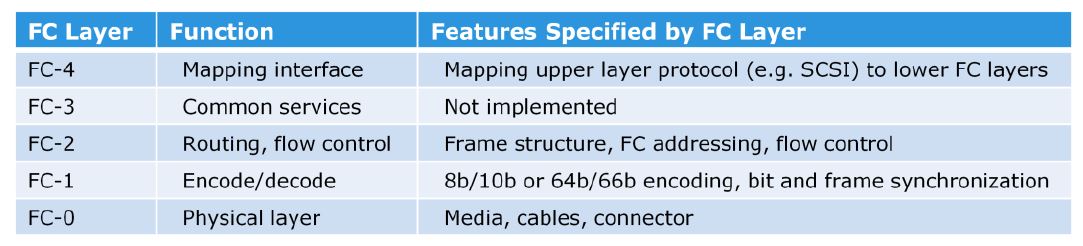
FC-1 Layer: It defines how data is encoded prior to transmission and decoded upon receipt. At the transmitter node, an 8-bit character is encoded into a 10-bit transmission character. This character is then transmitted to the receiver node. At the receiver node, the 10-bit character is passed to the FC-1 layer, which decodes the 10-bit character into the original 8-bit character. FC links, with a speed of 10 Gbps and above, use 64-bit to 66-bit encoding algorithm. This layer also defines the transmission words such as FC frame delimiters, which identify the start and the end of a frame and the primitive signals that indicate events at a transmitting port. In addition to these, the FC-1 layer performs link initialization and error recovery.
FC Addressing
An FC address is dynamically assigned when a node port logs on to the fabric. The FC address has a distinct format.

The first field of the FC address contains the domain ID of the switch. A domain ID is a unique number provided to each switch in the fabric. Although this is an 8-bit field, there are only 239 available addresses for domain ID because some addresses are deemed special and reserved for fabric services. For example, FFFFFC is reserved for the name server, and FFFFFE is reserved for the fabric login service.
Also Read: Fibre Channel over IP (FCIP) SAN Introduction
Also Read: Fibre Channel over IP (FCIP) SAN Introduction
The area ID is used to identify a group of switch ports used for connecting nodes. An example of a group of ports with common area ID is a port card on the switch.
The last field, the port ID, identifies the port within the group. Therefore, the maximum possible number of node ports in a switched fabric is calculated as:
239 domains X 256 areas X 256 ports = 15,663,104 ports.
FC Fabric
A fabric is a collection of connected FC switches that have a common set of services such as they can share a common name server, common zoning database and common FSPS routing table. You can also deploy dual redundant fabrics for resiliency. Each fabric is viewed and managed as a single logical entity and it is common across the fabric to update the zoning configuration from any switch in the fabric.


Every FC switch in a fabric needs a domain ID. This domain ID is a numeric string that is used to uniquely identify the switch in the fabric. These domain IDs can be administratively set or dynamically assigned by the principal switch in a fabric during reconfiguration. These Domain ID must be a unique IDs within a fabric and should be used for another switch.
Principal Switch is a main switch in a fabric that is responsible for managing the distribution of domain IDs within the fabric
FC Frame Strucutre
In an FC network, data transport is analogous to a conversation between two people, whereby a frame represents a word, a sequence represents a sentence, and an exchange represents a conversation.
Exchange: An exchange operation enables two node ports to identify and manage a set of information units. Each upper layer protocol (ULP) has its protocol-specific information that must be sent to another port to perform certain operations. This protocol-specific information is called an information unit. The structure of these information units is defined in the FC-4 layer. This unit maps to a sequence. An exchange is composed of one or more sequences.
Sequence: A sequence refers to a contiguous set of frames that are sent from one port to another. A sequence corresponds to an information unit, as defined by the ULP.
Frame: A frame is the fundamental unit of data transfer at FC-2 layer. An FC frame consists of five parts: start of frame (SOF), frame header, data field, cyclic redundancy check (CRC), and end of frame (EOF).
The SOF and EOF act as delimiters. The frame header is 24 bytes long and contains addressing information for the frame. The data field in an FC frame contains the data payload, up to 2,112 bytes of actual data – in most cases the SCSI data. The CRC checksum facilitates error detection for the content of the frame. This checksum verifies data integrity by checking whether the content of the frames are received correctly. The CRC checksum is calculated by the sender before encoding at the FC-1 layer. Similarly, it is calculated by the receiver after decoding at the FC-1 layer.
FC Services
All FC switches, regardless of the manufacturer, provide a common set of services as defined in the FC standards. These services are available at certain predefined addresses. Some of these services are Fabric Login Server, Fabric Controller, Name Server, and Management Server.
Fabric Login Server: It is located at the predefined address of FFFFFE and is used during the initial part of the node’s fabric login process.
Name Server (formally known as Distributed Name Server): It is located at the predefined address FFFFFC and is responsible for name registration and management of node ports. Each switch exchanges its Name Server information with other switches in the fabric to maintain a synchronized, distributed name service.
Also Read: Introduction to Fibre Channel over Ethernet (FCoE) SAN
Also Read: Introduction to Fibre Channel over Ethernet (FCoE) SAN
Fabric Controller: Each switch has a Fabric Controller located at the predefined address FFFFFD. The Fabric Controller provides services to both node ports and other switches. The Fabric Controller is responsible for managing and distributing Registered State Change Notifications (RSCNs) to the node ports registered with the Fabric Controller. If there is a change in the fabric, RSCNs are sent out by a switch to the attached node ports. The Fabric Controller also generates Switch Registered State Change Notifications (SW-RSCNs) to every other domain (switch) in the fabric. These RSCNs keep the name server up-to-date on all switches in the fabric.
Management Server: FFFFFA is the FC address for the Management Server. The Management Server is distributed to every switch within the fabric. The Management Server enables the FC SAN management software to retrieve information and administer the fabric.
Fabric services define three login types:
- Fabric login (FLOGI): It is performed between an N_Port and an F_Port. To log on to the fabric, a node sends a FLOGI frame with the WWNN and WWPN parameters to the login service at the predefined FC address FFFFFE (Fabric Login Server). In turn, the switch accepts the login and returns an Accept (ACC) frame with the assigned FC address for the node. Immediately after the FLOGI, the N_Port registers itself with the local Name Server on the switch, indicating its WWNN, WWPN, port type, class of service, assigned FC address, and so on. After the N_Port has logged in, it can query the name server database for information about all other logged in ports.
- Port login (PLOGI): It is performed between two N_Ports to establish a session. The initiator N_Port sends a PLOGI request frame to the target N_Port, which accepts it. The target N_Port returns an ACC to the initiator N_Port. Next, the N_Ports exchange service parameters relevant to the session.
- Process login (PRLI): It is also performed between two N_Ports. This login relates to the FC-4 ULPs, such as SCSI. If the ULP is SCSI, N_Ports exchange SCSI-related service parameters.
FC Flow Control
Flow control is the process to regulate the data transmission rate between two devices so that a transmitting device does not overflow a receiving device with data. A fabric uses the buffer-to-buffer credit (BB_Credit) mechanism for flow control. The BB_Credit management may occur between any two FC ports.
In a fabric, an FC frame is received and stored in a receive buffer where it is processed by the receiving FC port. If another frame arrives while the receiving port is processing the first frame, a second receive buffer is needed to hold the new frame. If all the receive buffers are filled up with received frames and the transmitting port sends another frame, then the receiving port would not have a receive buffer available to hold the new frame and the frame would be dropped. BB_Credit mechanism ensures that the FC ports do not run out of buffers and do not drop frames.
With BB_Credit mechanism, the transmitting and receiving ports agree on the number of buffers available or BB_Credits during the port login process. The credit value is decremented when a frame is transmitted and incremented upon receiving a response. A receiver ready (R_RDY) is sent from the receiving port to the transmitting port for every free buffer on the receiving side. The transmitting port increments the credit value per R_RDY it receives from the receiving port. The transmitting port maintains a count of available credits and continues to send frames if the count is greater than zero. If the available credits reaches zero, then further transmission of frames is suspended until the credit count becomes a nonzero value.
Previous: 4.2 Fibre Channel (FC) SAN Components
Previous: 4.2 Fibre Channel (FC) SAN Components
Go To >> Index Page
What Others are Reading Now...


Very useful overview of FC
ReplyDelete