2.3 Solid State Drive (SSD) Overview

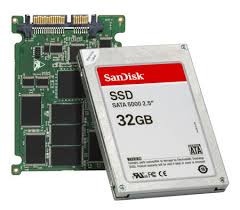
Solid State Drives (SSDs) are storage devices that contain non-volatile flash memory. Solid state drives are superior to mechanical hard disk drives (HDD) in terms of performance, power use, and availability. These drives are especially well suited for low-latency applications that require consistent, low (less than 1 ms) read/write response times. 

SSDs consume less power compared to hard disk drives. Because SSDs do not have moving parts, they generate less heat compared to HDDs. Therefore, it further reduces the need for cooling in storage enclosure, which further reduces the overall system power consumption.

Physical Solid State Drive (SDD) Structure

In a HDD servicing, small-block, highly-concurrent, random workloads involve considerable rotational and seek latency, which significantly reduces throughput. Externally solid state drives have the same physical format and connectors as mechanical hard disk drives. This maintains the compatibility in form and format with mechanical hard disk drives, and allows easy replacement of a mechanical drive with a solid state drive. Internally, a solid state drive’s hardware architecture consists of the following components: I/O interface, controller, and mass storage.

Solid State Drive (SSD) Components


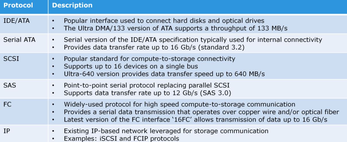
I/O interface: The I/O interface enables connecting the power and data connectors to the solid state drives. SSDs typically support standard connectors such as SATA, SAS, or FC.

Controller: The controller includes a drive controller, RAM, and non-volatile memory (NVRAM). The drive controller manages all drive functions. The SSDs include many features such as encryption and write coalescing. The non-volatile RAM (NVRAM) is used to store the SSD’s operational software and data. Not all SSDs have separate NVRAM. Some models store their programs and data to the drive’s mass storage. The RAM is used in the management of data being read and written from the SSD as a cache, and for the SSD’s operational programs and data. The portion of the drive’s RAM used for controller cache enhances the overall performance of the SSD. Mass storage, which is made of flash memories, writes slower than it reads. The drive’s RAM is used to minimize the number of writes to mass storage and improve the response time of the drive.

Write coalescing is one of the techniques employed within the RAM. This is the process of grouping write I/Os and writing them in a single internal operation versus many smaller-sized write operations. In addition to caching, the RAM contains the drive controller’s operational software and mapping tables. Mapping tables correlate the internal data structure of the SSD to the file system data structure of the compute system.

Mass Storage (Flash Memory): The mass storage is an array of non-volatile memory chips. They retain their contents when powered off. These chips are commonly called Flash memory. The number and capacity of the individual chips vary directly in relationship to the SSD’s capacity. The larger the capacity of the SSD, the larger is the capacity and the greater is the number of the Flash memory chips.

The Flash memory chips that make up the drive’s mass storage come from numerous manufacturers. Two types of Flash memory chip are used in commercially available SSDs: Single-Level Cell (SLC) and Multi-Level Cell (MLC). SLC-type Flash is typically used in enterprise-rated SSDs for its increased memory speed and longevity. MLC is slower but has the advantage of greater capacity per chip. Although SLC type Flash memory offers a lower density, it also provides a higher level of performance in the form of faster reads and writes. In addition, SLC Flash memory has higher reliability. As SLC Flash memory stores only one bit per cell, the likelihood for error is reduced. SLC also allows for higher write/erase cycle endurance. For these reasons, SLC Flash memory is preferred for use in applications requiring higher reliability, and increased endurance and viability in multi-year product life cycles.

SSDs have multiple parallel I/O channels from its drive controller to the flash memory storage chips. Generally, the larger the number of flash memory chips in the drive, the larger is the number of channels. The larger the number of channels, the greater is the SSD’s internal bandwidth. The drive’s controller uses native command queuing to efficiently distribute read and write operations across all available channels. Bandwidth performance scales upward with parallel use of all available channels. Note that the drives with the same capacity, but from different vendors, can have a different number of channels. These drives will have different levels of performance. The drive with more channels will outperform the drive with a fewer under some circumstances.

Solid State Drive (SSD) Addressing

Solid state memory chips have different capacities, for example a solid state memory chip can be 32 GB or 4 GB per chip. However, all memory chips share the same logical organization, that is pages and blocks.

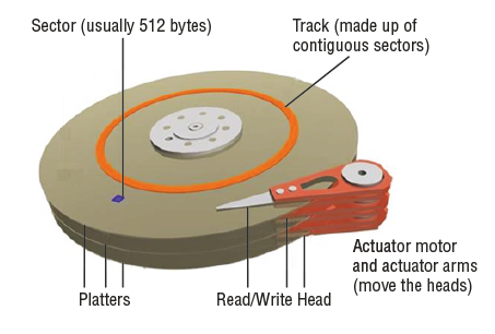
At the lowest level, a solid state drive stores bits. Eight bits make up a byte, and while on the typical mechanical hard drive 512 bytes would make up a sector, solid state drives do not have sectors. Solid state drives have a similar physical data object called a page. Like a mechanical hard drive sector, the page is the smallest object that can be read or written on a solid state drive. Unlike mechanical hard drives, pages do not have a standard capacity. A page’s capacity depends on the architecture of the solid state memory chip. Typical page capacities are 4 KB, 8 KB, and 16 KB.

A solid state drive block is made up of pages. A block may have 32, 64, or 128 pages. 32 is a common block size. The total capacity of a block is dependent on the solid state chip’s page size. Only entire blocks may be written or erased on a solid state memory chip. Individual pages may be read or invalidated (a logical function). For a block to be written, pages are assembled into full blocks in the solid state drive’s cache RAM and then written to the block storage object.

Page and Block Concepts in SSD

PAGE: A page has three possible states, erased (empty), valid, and invalid. In order to write any data to a page, its owning block location on the flash memory chip must be electrically erased. This function is performed by the SSD’s hardware. Once a page has been erased, new data can be written to it. For example, when a 4 KB of data is written to a 4 KB capacity page, the state of that page is changed to valid, as it is holding valid data. A valid page’s data can be read any number of times. If the drive receives a write request to the valid page, the page is marked invalid and that write goes to another page. This is because erasing blocks is time consuming and may increase the response time. Once a page is marked invalid, its data can no longer be read. An invalid page needs to be erased before it can once again be written with new data. Garbage collection handles this process. Garage collection is the process of providing new erased blocks.

BLOCK: A block has three possible states, erased (empty), new, and used. Once a block is erased, a block’s number of pages that have been assembled in the SSD’s RAM may be written to it. For example, thirty two 4 KB pages may be assembled into a block, and then written to the erased block. This sets the block’s state to “new”, meaning it is holding pages with valid data. A block’s valid pages can be read any number of times. There are two mechanisms to invalidate a page, writes and deletes. If the drive receives a write request to a valid block page, the page must be changed. The current page containing the destination of the write is marked invalid. The block’s state changes to “used”, because it contains invalid pages. These writes go to another page, on an erased block. A delete invalidates a page without resulting in a subsequent write.

Performance of an Solid State Drive (SSD)

Solid state drives are semiconductor, random-access devices; these result in very low response times compared to hard disk drives. This, combined with the multiple parallel I/O channels on the back end, gives SSDs performance characteristics that are better than HDDs.

SSD performance is dependent on access type, drive state, and workload duration. SSD performs random reads the best. In carefully tuned multi-threaded, small-block random I/O workload storage environments, SSDs can deliver much lower response times and higher throughput than HDDs. This is because random-read I/Os cannot usually be serviced by read-ahead algorithms on a HDD or by read cache on the storage system. 

The latency of a random read operation is directly related to the seek time of a HDD. For HDDs, this is the physical movement of the drive’s read/write head to access the desired area. Because they are random access devices, SSDs pay no penalty for retrieving I/O that is stored in more than one area; as a result their response time is in an order of magnitude faster than the response time of HDDs.

For large block I/Os, SSDs tend to use all internal I/O channels in parallel. Since the single-threaded sequential I/O streams on FC HDDs do not suffer seek and rotational latencies because of the storage system cache, single-threaded large-block sequential I/O streams will not show major performance improvements with SSDs over FC HDDs. 

However, with the increased application concurrency (as more threads are added), the load starts to resemble a large block-random workload. In this case, seek and rotational latencies are introduced that decrease the FC HDD effectiveness but do not decrease SSD effectiveness.

A new SSD or an SSD with substantial unused capacity has the best performance. Drives with substantial amounts of their capacity consumed will take longer to complete the read-modify-write cycle. SSDs are best for workloads with short bursts of activity.

Previous: 2.2 ElectroMechanical Hard Disk Drive (HDD) Overview

                                                                       Next: 2.4 What is a Storage Array

2.2 ElectroMechanical Hard Disk Drive (HDD) Overview

A hard disk drive is a persistent storage device that stores and retrieves data using rapidly rotating disks (platters) coated with magnetic material. The key components of a hard disk drive (HDD) are platter, spindle, read-write head, actuator arm assembly, and controller board. 

I/O operations in an HDD are performed by rapidly moving the arm across the rotating flat platters coated with magnetic material. Data is transferred between the disk controller and magnetic platters through the read-write (R/W) head which is attached to the arm. Data can be recorded and erased on magnetic platters any number of times.

Hard Disk Drive (HDD) Strucutre

Data on the disk is recorded on tracks, which are concentric rings on the platter around the spindle. Each track is divided into smaller units called sectors. A sector is the smallest, individually addressable unit of storage. 

The track and sector structure is written on the platter by the drive manufacturer using a low-level formatting operation. The number of sectors per track varies according to the drive type. There can be thousands of tracks on a platter, depending on the physical dimensions and the recording density of the platter. 

Typically, a sector holds 512 bytes of user data; although some disks can be formatted with larger sector sizes. In addition to user data, a sector also stores other information, such as the sector number, head number or platter number, and track number. This information helps the controller to locate the data on the drive. 

Hard Disk Drive (HDD) Components

Platter: A typical HDD consists of one or more flat circular disks called platters. The data is recorded on these platters in binary codes (0s and 1s). The set of rotating platters is sealed in a case, called Head Disk Assembly (HDA). A platter is a rigid, round disk coated with magnetic material on both surfaces (top and bottom). The data is encoded by polarizing the magnetic area or domains of the disk surface. Data can be written to or read from both surfaces of the platter. The number of platters and the storage capacity of each platter determine the total capacity of the drive.

Spindle: A spindle connects all the platters and is connected to a motor. The motor of the spindle rotates with a constant speed. The disk platter spins at a speed of several thousands of revolutions per minute (rpm). Common spindle speeds are 5,400 rpm, 7,200 rpm, 10,000 rpm, and 15,000 rpm. The speed of the platter increases with the improvement in technology; although the extent to which it can be improved is limited.

Read/Write Head: This component will read and write data from or to the platters. Drives have two R/W heads per platter, one for each surface of the platter. The R/W head changes the magnetic polarization on the surface of the platter when writing data. While reading data, the head detects the magnetic polarization on the surface of the platter. During reads and writes, the R/W head senses the magnetic polarization and never touches the surface of the platter. When the spindle rotates, a microscopic air gap is maintained between the R/W heads and the platters, known as the head flying height. This air gap is removed when the spindle stops rotating and the R/W head rests on a special area on the platter near the spindle. This area is called the landing zone. The landing zone is coated with a lubricant to reduce friction between the head and the platter. The logic on the disk drive ensures that heads are moved to the landing zone before they touch the surface. If the drive malfunctions and the R/W head accidentally touches the surface of the platter outside the landing zone, a head crash occurs. In a head crash, the magnetic coating on the platter is scratched and may cause damage to the R/W head. A head crash generally results in data loss.

Actuator arm assembly: R/W heads are mounted on the actuator arm assembly, which positions the R/W head at the location on the platter where the data needs to be written or read. The R/W heads for all platters on a drive are attached to one actuator arm assembly and move across the platters simultaneously.

Drive controller board: The controller is a printed circuit board, mounted at the bottom of a disk drive. It consists of a microprocessor, internal memory, circuitry, and firmware. The firmware controls the power supplied to the spindle motor as well as controls the speed of the motor. It also manages the communication between the drive and the compute system. In addition, it controls the R/W operations by moving the actuator arm and switching between different R/W heads, and performs the optimization of data access.

Logical Block Addressing (LBA)

The earlier drives used physical addresses consisting of cylinder, head, and sector (CHS) number to refer to specific locations on the disk, and the OS had to be aware of the geometry of each disk used. Logical block addressing (LBA) has simplified the addressing by using a linear address to access physical blocks of data. The disk controller translates LBA to a CHS address, and the servers needs to know only the size of the disk drive in terms of the number of blocks. The logical blocks are mapped to physical sectors on a 1:1 basis. 

Performance of an Hard Disk Drive

A disk drive is an electromechanical device that governs the overall performance of the storage system environment. Determining storage requirements for an application begins with determining the required storage capacity and I/O performance. 

Capacity can be easily estimated by the size and number of file systems and database components used by applications. The I/O size, I/O characteristics, and the number of I/Os generated by the application at peak workload are other factors that affect performance, I/O response time and design of storage system.The various factors that affect the performance of disk drives are

Seek Time: The seek time (also called access time) describes the time taken to position the R/W heads across the platter moving along the radius of the platter. In other words, it is the time taken to position and settle the arm and the head over the correct track. Therefore, the lower the seek time, the faster the I/O operation. Each of these specifications is measured in milliseconds (ms). The seek time of a disk is typically specified by the drive manufacturer. Seek time has more impact on the I/O operation of random tracks rather than the adjacent tracks.

Rotational Latency: To access data, the actuator arm moves the R/W head over the platter to a particular track while the platter spins to position the requested sector under the R/W head. The time taken by the platter to rotate and position the data under the R/W head is called rotational latency. This latency depends on the rotation speed of the spindle and is measured in milliseconds. The average rotational latency is one-half of the time taken for a full rotation. Similar to the seek time, rotational latency has more impact on the reading/writing of random sectors on the disk than on the same operations on adjacent sectors.

Data Transfer Rate: The data transfer rate also called transfer rate refers to the average amount of data per unit time that the drive can deliver to the HBA. In a read operation, the data first moves from disk platters to R/W heads; then it moves to the drive’s internal buffer. Finally, data moves from the buffer through the interface to the compute system’s HBA. In a write operation, the data moves from the HBA to the internal buffer of the disk drive through the drive’s interface. The data then moves from the buffer to the R/W heads. Finally, it moves from the R/W heads to the platters. The data transfer rates during the R/W operations are measured in terms of internal and external transfer rates. Internal transfer rate is the speed at which data moves from a platter’s surface to the internal buffer (cache) of the disk. The internal transfer rate takes into account factors such as the seek time and rotational latency. External transfer rate is the rate at which data can move through the interface to the HBA.

Disk I/O Controller

The utilization of a disk I/O controller has a significant impact on the I/O response time. The I/O requests arrive at the controller at the rate generated by the application. The I/O arrival rate, the queue length, and the time taken by the I/O controller to process each request determines the I/O response time. If the controller is busy or heavily utilized, the queue size will be large and the response time will be high.

As the utilization reaches 100 percent, that is, as the I/O controller saturates, the response time moves closer to infinity. In essence, the saturated component or the bottleneck forces the serialization of I/O requests; meaning, each I/O request must wait for the completion of the I/O requests that preceded it. When the average queue sizes are low, the response time remains low. The response time increases slowly with added load on the queue and increases exponentially when the utilization exceeds 70 percent. Therefore, for performance-sensitive applications, it is common to utilize disks below their 70 percent of I/O serving capability.

Previous: 2.1 Types of Storage Devices used in Storage Arrays

                                                                            Next: 2.3 Solid State Drive (SSD) Overview

2.1 Types of Storage Devices used in Storage Arrays

There are different types of storage devices which can be used for storing the data and based upon the business requirement & cost, storage devices are selected to be used in the storage system or storage array. There are three main types of media or storage devices which are currently used as a storage medium in the data centres.
  • Disk media
  • Solid-state media
  • Tape Media

Disk media refers to the electro-mechanical hard disk drive and most people refer to it as a disk drive, hard drive, or hard disk drive (HDD). Solid-state media refers to a flash memory–based storage or SSD, but other forms of solid-state media also exist. Tape media refers to magnetic tape to store the data. Below is the overview of the various storage media and we will discuss in deep about HDD & SSD in next posts.

Types of Storage Devices


Magnetic Tape:

A magnetic tape is a thin, long strip of plastic film that is coated with a magnetizable material, such as barium ferrite. The tape is packed in plastic cassettes and cartridges. A tape drive is the device to record and retrieve data on a magnetic tape. 

Magnetic TapeTape drives provide linear sequential read/write data access. A tape drive may be standalone or part of a tape library. Tape is a popular medium for long-term storage due to its relative low cost and portability. Tape drives are typically used by organizations to store large amounts of data, typically for backup, offsite archiving, and disaster recovery. 

The low access speed due to the sequential access mechanism, the lack of simultaneous access by multiple applications, and the degradation of the tape surface due to the continuous contact with the read/write head are some of the key limitations of tape.


Mechanical Disk Drive:

A magnetic disk is a circular storage medium made of non-magnetic material and coated with a ferromagnetic material. Data is stored on both surfaces of a magnetic disk by polarizing a portion of the disk surface. 

A disk drive is a device that comprises multiple rotating magnetic disks, called platters, stacked vertically inside a metal or plastic casing. Each platter has a rapidly moving arm to read from and write data to the disk. Disk drives are currently the most popular storage medium for storing and accessing data for performance-intensive applications. 

Disks support rapid access to random data locations and data can be written or retrieved quickly for a number of simultaneous users or applications. Disk drives use pre-defined protocols such as 
  • Advanced Technology Attachment (ATA)
  • Serial ATA (SATA)
  • Small Computer System Interface (SCSI)
  • Serial Attached SCSI (SAS)
  • Fibre Channel (FC)
These protocols reside on the disk interface controllers that are typically integrated with the disk drives. Each protocol has its unique performance, cost, and capacity characteristics.


Solid-State Drive (SSD):

A solid-state drive (SSD) uses semiconductor-based memory, such as NAND and NOR chips, to store data. SSDs, also known as “flash drives”, deliver the ultra-high performance required by performance-sensitive applications. 

These devices, unlike conventional mechanical disk drives, contain no moving parts and therefore do not exhibit the latencies associated with read/write head movement and disk rotation. Compared to other available storage devices, SSDs deliver a relatively higher number of input/output operations per second (IOPS) with very low response times. 

They also consume less power and typically have a longer lifetime as compared to mechanical drives. However, flash drives do have the highest cost per gigabyte ratio.


Optical Disc

An optical disc is a flat, circular storage medium made of polycarbonate with one surface having a special, reflective coating such as aluminum. An optical disc drive uses a writing laser to record data on the disc in the form of microscopic light and dark dots. 

Optical Disc
A reading laser reads the dots, and generates electrical signals representing the data. The common optical disc types are compact disc (CD), digital versatile disc (DVD), and Blu-ray disc (BD). These discs may be recordable or re-writable. 

Recordable or read-only memory (ROM) discs have Write Once and Read Many (WORM) capability and are typically used as a distribution medium for applications or as a means to transfer small amounts of data from one system to another. The limited capacity and speed of optical discs constrain their use as a general-purpose enterprise data storage solution. However, high-capacity optical discs are sometimes used as a storage solution for fixed-content and archival data. 


Hybrid Drives

Hybrid Drives are relatively new type of drives which are not commonly used in datacenters yet. This is the combination of the best of both mechanical drives and solid state drives. They have both a rotating platter and solid-state memory (flash). 

Hybrid Dive
Most hybrid hard drives work on a simple caching technique. The most accessed sets of data will move from the spinning disk area to the solid-state area of the drive so that the data can be accessed much faster. But the drawback of this type of drives is when it comes to newly written data, newly written data is typically written to spinning disk first and then after a while of being frequently accessed, the data will move to solid-state memory. 

Some hybrid drives work in reverse fashion as well, the data is first written in solid-state area and then it will move down to mechanical disk area if not frequently accessed. However, both the approaches have their positive and negative feedbacks. 

Hybrid drives tries to bring both capacity and speed in single storage device and the inbuilt firmware will decide which data to move to solid-state area and which data goes into mechanical disk area. Hybrid drives are popular in personal desktop and computers but not commonly used in enterprise servers and storage arrays.


                                                Next: 2.2 ElectroMechanical Hard Disk Drive (HDD) Overview

2.6 What are Intelligent Storage Systems ?

Storage Arrays which are feature-rich RAID arrays that provide highly optimized I/O processing capabilities are generally referred as Intelligent Storage Arrays or Intelligent Storage Systems. These intelligent storage systems have the capability to meet the requirements of today’s I/O intensive next generation applications. These applications require high levels of performance, availability, security, and scalability. Therefore, to meet the requirements of the applications many vendors of intelligent storage systems now support SSDs, encryption, compression, deduplication, and scale-out architecture. 

The use of SSDs and scale-out architecture enable to service massive number of IOPS. These storage systems also support connectivity to heterogeneous compute systems. Further, the intelligent storage systems support APIs to enable integration with Software-Defined Data Cneter (SDDC) and cloud environments.

Intelligent Storage Systems Overview

These storage systems have an operating system that intelligently and optimally handles the management, provisioning, and utilization of storage resources. The storage systems are configured with a large amount of memory called cache and multiple I/O paths and use sophisticated algorithms to meet the requirements of performance-sensitive applications. An intelligent storage system has two key components, controller and storage. 

A controller is a compute system that runs a purpose-built operating system that is responsible for performing several key functions for the storage system. Examples of such functions are serving I/Os from the application servers, storage management, RAID protection, local and remote replication, provisioning storage, automated tiering, data compression, data encryption, and intelligent cache management.

An intelligent storage system typically has more than one controller for redundancy. Each controller consists of one or more processors and a certain amount of cache memory to process a large number of I/O requests. These controllers are connected to the servers either directly or via a storage network. The controllers receive I/O requests from the servers that are read or written from/to the storage by the controller. 

Based on the type of data access, a storage system can be classified as block-based storage system, file-based storage system, object-based storage system, and unified storage system. A unified storage system provides block-based, file-based, and object-based data access in a single system. These are described in the next posts.


Architecture of Intelligent Storage Systems

An intelligent storage system may be built either based on scale-up or scale-out architecture.

A scale-up storage architecture provides the capability to scale the capacity and performance of a single storage system based on requirements. Scaling up a storage system involves upgrading or adding controllers and storage. These systems have a fixed capacity ceiling, which limits their scalability and the performance also starts degrading when reaching the capacity limit.

scaleup and scaleout storage sytems


A scale-out storage architecture provides the capability to maximise its capacity by simply adding nodes to the cluster. Nodes can be added quickly to the cluster, when more performance and capacity is needed, without causing any downtime. This provides the flexibility to use many nodes of moderate performance and availability characteristics to produce a total system that has better aggregate performance and availability. Scale-out architecture pools the resources in the cluster and distributes the workload across all the nodes. This results in linear performance improvements as more nodes are added to the cluster.


Features of an Intelligent Storage Systems

Storage Tiering
Storage tiering is a technique of establishing a hierarchy of different storage types (tiers). This enables storing the right data to the right tier, based on service level requirements, at a minimal cost. Each tier has different levels of protection, performance, and cost. 


This technique allows us to place data on the most appropriate tier of storage. It helps to place frequently accessed data on fast media and inactive data on slow media. This can improve the performance of the storage array and bring costs down by not having to fill array with fast disks when most of the data is relatively infrequently accessed. This movement of data happens based on defined tiering policies. The tiering policy might be based on parameters, such as frequency of access.

For example, high performance solid-state drives (SSDs) or FC drives can be configured as tier 1 storage to keep frequently accessed data and low cost SATA drives as tier 2 storage to keep the less frequently accessed data. Keeping frequently used data in SSD or FC improves application performance. Moving less-frequently accessed data to SATA can free up storage capacity in high performance drives and reduce the cost of storage. 


The process of moving the data from one type of tier to another is typically automated. In automated storage tiering, the application workload is proactively monitored; the active data is automatically moved to a higher performance tier and the inactive data is moved to higher capacity, lower performance tier. The data movement between the tiers is performed non-disruptively.


Redundancy

Redundancy feature in a intelligent storage system ensure that failed components do not interrupt the operation of the array. Even at the host level, multiple paths are usually configured between the host and storage in multipath I/O configurations, ensuring that the loss of a path or network link between the host and storage array does not take the system down.

Replication
Storage  system based replication makes remote copies of production volumes that can play a vital role in disaster Recovery (DR) and business continuity (BC) planning. Depending on the application and business requirements, remote replicas can either be zero-loss synchronous replicas. Asynchronous replication technologies can have thousands of miles between the source and target volumes but synchronous replication requires the source and target to be not more than 100 miles.

Thin Provisioning
Thin provisioning technologies can be used to more effectively utilise the capacity in the storage systems. Over provisioning of storage space would eventually result in running out of available space.


Previous: 2.5 Storage Array Architecture

                                              
                                              Next:  2.7 Accessing data from the Intelligent Storage Systems

1.10 Storage Connectivity and Network Virtualization Overview

In general, network connectivity is the process of connecting various components in a network to one another through the use of routers, switches and gateways. Similarly, storage network connectivity refers to the communication paths between IT infrastructure components for information exchange and resource sharing. The two primary types of connectivity include the interconnection between servers and between a server and storage. Since our discussion is related to storage, we will discuss only about connection between server and storage devices.

Server-to-Server Connectivity

Server to Server connectivity typically uses protocols based on the Internet Protocol (IP). Each physical server is connected to a network through one or more host interface devices, called a network interface controller (NIC). Physical switches and routers are the commonly-used interconnecting devices. 

A switch enables different servers in the network to communicate with each other. A router is an OSI Layer-3 device that enables different networks to communicate with each other. The commonly-used network cables are copper cables and optical fiber cables. It is necessary to ensure that appropriate switches and routers, with adequate bandwidth and ports, are available to provide the required network performance.

Server-to-Storage Connectivity

Connectivity and communication between server and storage are enabled through physical components and interface protocols. The physical components that connect servers to storage are host interface device, port, and cable.


server-storage connectivity


Host bus Adapter (HBA): A host bus adapter (HBA) is a host interface device that connects a compute system to storage or to a SAN. It is an application-specific integrated circuit (ASIC) board that performs I/O interface functions between a compute system and storage, relieving the processor from additional I/O processing workload. A server typically contains multiple HBAs.

Port: A port is a specialized outlet that enables connectivity between the server and storage. An HBA may contain one or more ports to connect the server to the storage. Cables connect server to internal or external devices using copper or fiber optic media.

Protocol: A protocol enables communication between the server and storage. Protocols are implemented using interface devices (or controllers) at both the source and the destination devices. The popular interface protocols used for server-to-storage communication are Integrated Device Electronics/Advanced Technology Attachment (IDE/ATA), Small Computer System Interface (SCSI), Fibre Channel (FC) and Internet Protocol (IP). These are discussed below

Storage Connectivity Protocols

Integrated Device Electronics (IDE)/Advanced Technology Attachment (ATA): It is a popular interface protocol standard used for connecting storage devices, such as disk drives and optical drives. This protocol supports parallel transmission and therefore is also known as Parallel ATA (PATA) or simply ATA. 

IDE/ATA has a variety of standards and names. In a master-slave configuration, an ATA interface supports two storage devices per connector. However, if the performance of the drive is important, sharing a port between two devices is not recommended.

Serial ATA (SATA): The serial version of this protocol supports single bit serial transmission and is known as Serial ATA (SATA). High performance and low cost SATA has largely replaced PATA in the newer systems. SATA revision 3.2 provides a data transfer rate up to 16 Gb/s.

Small Computer System Interface (SCSI): SCSI has emerged as a preferred connectivity protocol in high-end servers. This protocol supports parallel transmission and offers improved performance, scalability, and compatibility compared to ATA. However, the high cost associated with SCSI limits its popularity among home or personal desktop users. Over the years, SCSI has been enhanced and now includes a wide variety of related technologies and standards. SCSI supports up to 16 devices on a single bus and provides data transfer rates up to 640 MB/s.

Storage Connectivity Protocols


Serial attached SCSI (SAS): It is a point-to-point serial protocol that provides an alternative to parallel SCSI. A newer version (SAS 3.0) of serial SCSI supports a data transfer rate up to 12 Gb/s.

Fibre Channel (FC): Fibre Channel is a widely-used protocol for high-speed communication to the storage device. The Fibre Channel interface provides gigabit network speed. It provides a serial data transmission that operates over copper wire and optical fiber. The latest version of the FC interface ‘16FC’ allows transmission of data up to 16 Gb/s. 

Internet Protocol (IP): IP is a network protocol that has been traditionally used for server-to-server traffic. With the emergence of new technologies, an IP network has become a viable option for server-to-storage communication. IP offers several advantages in terms of cost and maturity and enables organizations to leverage their existing IP-based network. iSCSI and FCIP protocols are common examples that leverage IP for server-to-storage communication.

Virtualizing the Storage Network Connection

Just as we can virtualize the physical servers and the storage devices to provision logical virtual servers and storage, we can also virtualize the network connection to create virtual network resources.

Network virtualization is the technique of abstracting physical network resources to create virtual network resources. Network virtualization software is either built into the operating environment of a network device, installed on an independent compute system or available as hypervisor’s capability. Network virtualization software has the ability to abstract the physical network resources such as switches and routers to create virtual resources such as virtual switches.


Network Virtualization


It also has the ability to divide a physical network into multiple virtual networks, such as virtual LANs and virtual SANs. Network virtualization available as a hypervisor’s capability can emulate the network connectivity between virtual machines (VMs) on a physical server. It also enables creating virtual switches that appear to the VMs as physical switches.

Network virtualization solutions can consolidate multiple physical networks into one virtual network. They can also logically segment a single physical network into multiple logical networks. Partitions can be added to rapidly scale the network for business needs. Some of the benefits of virtualizing the storage network are to

  • Enhance enterprise agility
  • Improve network efficiency
  • Reduce capital and operational costs
  • Maintain high standards of security, scalability, manageability, and availability throughout the network design.


                                                    Next: 2.1 Types of Storage Devices used in Storage Arrays

1.9 Storage Virtualization Overview

Similarly, just as we can virtualize the physical servers and applications we can also virtualize the storage systems to access the data. Storage Virtualization can be defined as the pooling of physical storage from multiple network storage devices into what appears to be a single storage device that is managed from a central console.

What is Storage Virtualization ?

Storage virtualization is the technique of abstracting physical storage resources like SSD's and HDD's to create virtual storage resources. Storage virtualization software has the ability to pool and abstract physical storage resources, and present them as a logical storage resources, such as virtual volumes, virtual disk files, and virtual storage systems. According to SNIA (Storage Networking Industry Association), There are 3 types of storage virtualization. 


Host-Based Storage Virtualization: 

Host-based virtualization is usually in the form of a logical volume manager on a host that aggregates and abstracts volumes into virtual volumes called logical volumes. Volume managers also provide advanced storage features such as snapshots and replication, but they are limited in scalability, as they are tied to a single host. Most companies don’t consider host-based storage virtualization as a true form of storage virtualization.

Network-Based (SAN-Based) Storage Virtualization: 

Network-Based storage virtualization is virtualizing storage at the SAN switch level which is a very complex type of storage virtualization and also rarely used by companies. At the network layer, it requires intelligent network switches, or SAN-based appliances, that perform functions aggregation and virtualization of storage arrays, combining LUNS from heterogeneous arrays into a single LUN and allowing heterogeneous replication at the fabric level which replicating between different array technologies. 

Controller-Based Storage Virtualization 

This is by far the most common form of storage virtualization and consists of an intelligent storage controllers that can virtualize the storage disks. The SNIA categorizes controller-based storage virtualization as either in-band or out-of-band. 

In In-band virtualization, the technology performing the virtualization sits directly in the data path. This means that all I/O of user data and control data passes through the technology performing the virtualization. Whereas Out-of-band virtualization which is also known as asymmetric has the meta data pass through a virtualization device or appliance and usually require special HBA drivers and agent software deployed on the host. It is less popular than In-band virtualization.

Advantages of Storage Virtualization

As with Server & Application virtualization, storage virtualization enhances your organization’s efficiency and agility and makes storage protection infinitely easier than with traditional physical storage architectures. These are the common benefits an oraganization can get by deploying storage virtualization.

  • Agility: By breaking down the barriers between physical storage devices and creating a single storage pool and management interface, storage virtualization makes provisioning new storage for new company initiatives infinitely simpler. The management interface masks the underlying complexity of the physical storage devices, so you no longer have to deal with the individual quirks of each storage device. You don’t even have to know which devices you’re using. Instead, you can add or migrate storage simply by clicking on icons in a software application. Provisioning new storage is quick and painless, so you can respond to new business initiatives fast.
  • Efficiency: Intimately tied with agility is storage efficiency. Since provisioning and migration are so much easier, companies are no longer inclined to over provision storage in order to prevent time consuming upgrades.   
  • Thin Provisioning: Many storage virtualization solutions enable a feature called thin provisioning that makes provisioning even more painless and increases storage efficiency further. Thin provisioning allows file systems to pull new storage from a shared storage pool instantly at the moment they need to write to it, or based on thresholds you configure in advance. 
  • Performance: Some storage virtualization solutions let you stripe data across multiple drives, drive arrays, and network storage devices, regardless of different physical storage brands and products. This can enhance performance tremendously for high performance applications such as video manipulation.
  • Easy Management: Since storage virtualization pools storage from different devices and brands and presents it all under a single management interface, it makes managing storage much easier. You only have to master one interface instead of multiple. Troubleshooting storage issues is infinitely quicker and easier as well.  
  • Reduced Costs: Storage virtualization reduces both the capital and ongoing costs of storage. Since you’re no longer over provisioning storage, your initial storage capital costs are greatly reduced. And since provisioning and managing storage take less time and training your ongoing costs are reduced. Less physical storage also means lower power and cooling costs.
  • Automation: Data center automation is a new software category that is coming into its own with the advent of storage and server virtualization. With data center automation software, new resources can be provisioned to applications automatically when they are needed, say at peak use points of the day, then removed when they are not. Users can actually use some automation solutions to provision their own server and storage resources for new projects or test configurations without even having to call on IT.
Having discussed all the above points about the usage and benefits of Storage Virtualization, all these are leading the current storage administration to a next level called Software-defined storage administration which we will discuss in next posts.

Software-defined storage (SDS) is a storage infrastructure that is managed and automated by software. SDS abstracts heterogeneous storage systems and their underlying capabilities, and pools the storage resources. Storage capacity is dynamically and automatically allocated from the storage pools based on policies to match the needs of applications.

Previous: 1.8 Server and Storage Architectures Overview

                                                     
                                                     Next: 1.10 Storage Connectivity and Network Virtualization

1.8 Server and Storage Architectures Overview

Based upon the type of storage-server architecture deployed, storage virtualization software is either built into the operating environment of a storage system, installed on an independent compute system, or available as hypervisor’s capability. There are two types of Server-Storage Architectures being used currently in a Data Center. 

Server-Centric Architecture:

This is a traditional server-storage architecture in which organizations have their own servers running the business applications. Storage devices are connected directly to the servers and are typically internal to the server. These storage devices cannot be shared with any other server. This is called server-centric storage architecture in other words known as Direct Attached Storage (DAS). 

In this architecture, each server has a limited number of storage devices, and each storage device exists only in relation to the server to which it is connected.


Server-centric architecture has several limitations, and is therefore inadequate to satisfy the growing demand for storage capacity in latest business environments. The number of storage devices that can be connected to one server is limited, and it is not possible to scale the storage capacity. 

Moreover, a server cannot directly access the unused storage space available on other servers. A server failure or any administrative tasks, such as maintenance of the server or increasing its storage capacity, also results in unavailability of information.

Information-Centric Architecture:

To overcome the challenges of the server-centric architecture, storage evolved to the information-centric architecture. In information-centric architecture, storage devices exist completely independently of servers, and are managed centrally and shared between multiple compute systems. Storage devices assembled within storage systems form a storage pool, and several compute systems access the same storage pool over a specialized, high-speed storage area network (SAN). 

information-centric architecture


A SAN is used for information exchange between compute systems and storage systems, and for connecting storage systems. It enables compute systems to share storage resources, improve the utilization of storage systems, and facilitate centralized storage management. SANs are classified based on protocols they support. Common SAN deployment types are below and are discussed in next posts

  • Fibre Channel SAN (FC SAN)
  • Internet Protocol SAN (IP SAN)
  • Fibre Channel over Ethernet SAN (FCoE SAN)

In this type of architecture, when a new server is deployed in the environment, storage is assigned to the server from the same shared pool of storage devices. The storage capacity can be increased dynamically and without impacting information availability by adding storage devices to the pool. This architecture improves the overall storage capacity utilization, while making management of information and storage more flexible and cost-effective.

Need for Virtualizing the Storage

One primary disadvantage of the above discussed architectures is that we have to login to each storage system to provision or manage the storage to the servers. For example, if an organization is having multiple vendors storage systems, the storage administrator should have multiple storage skills to manage the storage systems. 

Also since each vendor has their own interface to manage their storage box, the storage administrator has to know the way to use all the different storage vendors interfaces for managing and monitoring. This increases the complexity of managing the storage  in heterogeneous storage environment. 

In this fast pace cloud emerging environment, to overcome this complexity and delay in storage provisioning we have a technique called Storage Virtualization which will be discussed in next post.


Previous: 1.7 Server and Applications Virtualization Overview

                                                                                 Next: 1.9 Storage Virtualization Overview