4 August 2016

4.1 Introduction to SAN Protocols

The next generation IT platform is built on social networking, mobile computing, cloud services, and big data analytics technologies. Applications that support these technologies require significantly higher performance, scalability, and availability compared to the traditional applications. Storage technology solutions that can meet the these requirements  are:
  • Advanced Storage Area Network (SAN)
  • Different types of SAN implementations such as Fibre Channel (FC) SAN, Internet Protocol (IP) SAN, Fibre Channel over Ethernet (FCoE) SAN
  • Virtualization in SAN
  • Software-defined networking
We will look into all these SAN connectivity protocols in next 3 chapter. First let us understand what is SAN ?

What is Storage Area Network (SAN) ?

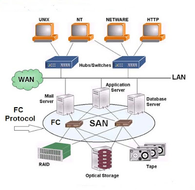
According to EMC definition, Storage area network (SAN) is a network that primarily connects the storage systems with the compute systems and also connects the storage systems with each other. It enables multiple compute systems to access and share storage resources. It also enables data transfer between the storage systems. With long-distance SAN, the data transfer over SAN can be extended across geographic locations. A SAN usually provides access to block-based storage systems.

SANs address the limitations of direct-attached storage (DAS) environment. Unlike a DAS environment, where the compute systems own the storage, SANs enable both consolidation and sharing of storage resources across multiple compute systems. This improves the utilization of storage resources compared to a DAS environment and reduces the total amount of storage that an organization needs to purchase and manage. With consolidation, storage management becomes centralized and less complex, which further reduces the cost of managing information.

A SAN may span over wide locations. This enables organizations to connect geographically dispersed compute systems and storage systems. The long-distance SAN connectivity enables the compute systems across locations to access shared data. The long-distance connectivity also enables the replication of data between storage systems that reside in separate locations. The replication over long-distances helps in protecting data against local and regional disaster. Further, the long-distance SAN connectivity facilitates remote backup of application data. Backup data can be transferred through a SAN to a backup device that may reside at a remote location.

These long distance SAN implementations is made possible by using various kind of SAN implementations such as Fibre Channel SAN (FC SAN).

What is Fibre Channel SAN (FC SAN) ?

Fibre Channel SAN (FC SAN) uses Fibre Channel (FC) protocol for communication. FC protocol (FCP) is used to transport data, commands, and status information between the compute systems and the storage systems. It is also used to transfer data between the storage systems.
Fibre Channel SAN
FC is a high-speed network technology that runs on high-speed optical fibre cables and serial copper cables. The FC technology was developed to meet the demand for the increased speed of data transfer between compute systems and mass storage systems.

The latest FC implementations of 16 GFC offer a throughput of 3200 MB/s (raw bit rates of 16 Gb/s), whereas Ultra640 SCSI is available with a throughput of 640 MB/s. FC is expected to come with 6400 MB/s (raw bit rates of 32 Gb/s) and 25600 MB/s (raw bit rates of 128 Gb/s) throughput in 2016. Technical Committee T11, which is the committee within International Committee for Information Technology Standards (INCITS), is responsible for FC interface standards.

The flow control mechanism in FC SAN delivers data as fast as the destination buffer is able to receive it, without dropping frames. FC also has very little transmission overhead. The FC architecture is highly scalable, and theoretically, a single FC SAN can accommodate approximately 15 million devices.

Previous: 3.9 The next generation RAID techniques
3.9 The next generation RAID techniques
The use of RAID technology started approximately 20 years ago and there are no significant advancements on the RAID technology till last 5-6 years. The common disk drive bloat problems and other disk slow performance issues lead to a longer rebuild times in a disk failure situation. This shows that the older RAID technologies are not suitable to provide uninterrupted business and IT needs. After the introduction of cloud computing and big data, this need has become a necessity to work on the new RAID techniques. 

To address these next generation IT demands, there are few interesting and important new RAID techniques have evolved and some of these also include the popular implementation forms of parallel and distributed RAID. Below are some of the interesting and popular new RAID techniques used in the current IT industry.

1) IBM XIV and RAID-X

IBM XIV is a storage array which implements a form of RAID 1 technology known as RAID-X. It is a turbo-charged, object-based distributed RAID and it is susceptible to double drive failures and allocates 50% of its capacity to protection. 

Object-based means that RAID protection is based on objects rather than entire drives, these objects are generally 1MB extents known as partitions. Each volume on an XIV is made up of multiple 1 MB extents and it is these 1 MB extents which are protected by RAID-X. The object-based nature of RAID-X enables the 1 MB extents that make up RAID-X volumes to be spread out across all the drives of the XIV array. This wide spreading of volumes across the entire backend leads to massively parallel reads, writes and re-protect operations. 

RAID-X offers a parallel reprotection operation which can reprotect the damaged extents to rebuild the original data.  If a drive in an XIV fails, RAID-X does not attempt to rebuild the failed drive but instead it starts working/reprotecting the affected data. To protect the damaged or lost extents, XIV reads each extent from all drives on the backend and writes new mirror copies of them to other drives spread across the entire backend in parallel. The RAID-X also ensures that the primary and mirror copies of any of the 1 MB extents are never saved in the same drive and it goes further to ensure that they are also on separate nodes or shelves. 

This reprotect operation runs parallely very fast and completes in just few minutes, the speed of the reprotect operation is vital to the viability of RAID-X at such large scale as it massively reduces the window of vulnerability to a second simultaneous drive failure. Also the parallel nature of a RAID-X rebuild avoids the increased load stress which is physically placed on all disks in the RAID set during normal RAID rebuild operations.

Since, RAID-X is object based, it reprotects only actual data. Non-object-based RAID techniques will often spend more time rebuilding tracks that have no data on them. By reprotecting only data, RAID-X speeds up reprotect operations. Once the data is reprotected, RAID-X will start rebuilding the failed drive which is a many-to-one operation (reprotected data comes from many drives to single drive).

Other object-based rebuilds or storage arrays such as HP 3PAR, Dell Compellent and XIO also use this kind of RAID approach but they use object-based RAID with parity and double parity rather than object based mirroring technique. 

2) ZFS and RAID-Z

RAID-Z is a parity-based RAID technique which is tightly integrated with the ZFS filesystem. It offers single, doube and triple parity options and uses a dynamic stripe width. This dynamic, variable-sized width is powerful, effectively enabling every RAID-Z write to be a full stripe write with the exception of small writes that are usually mirrored. RAID-Z has brilliant performance and rarely suffers from the read-modify-write penalty which traditional parity-based RAID techniques suffers when performing small-block writes.

RAID-Z rebuilds are significantly more complex than typical parity-based rebuilds where simple XOR calculations are performed against each RAID stripe. Because of the variable size of RAID-Z stripes, RAID-Z needs to query the ZFS filesystem to obtain information about the RAID-Z layout. This can cause longer rebuild times if the pool is near capacity or busy. Additionally, because RAID-Z and the ZFS filesystem talk to each other, rebuild operations rebuild only actual data and do not waste time rebuilding empty blocks.

3) RAID-TM

RAID-TM is a triple-mirror-based RAID. Instead of keeping two copies of data as in RAID 1 mirror sets, RAID-TM keeps three copies. As such, it loses 2/3 of capacity to protection but provides good performance and excellent protection.

4) RAID 7

The idea behind RAID 7 is to take RAID 6 one step further by adding a third set of parity  to protect data on increasingly larger and larger drives. 

5) RAIN

RAIN is an acronym for redundant/reliable array of inexpensive nodes. It is a form of network-based fault tolerance, where nodes are the basic unit of protection rather than drives or extents. RAIN-based approaches to fault tolerance are increasingly popular in scale-out filesystems, object-based storage, and cloud-based technologies. 

6) Erasure Codes Technique

Erasure codes also work slightly differently from parity. While parity separates the parity (correction codes) from the data, erasure codes expand the data blocks so that they include both real data and correction codes. Similar to RAID, erasure codes offer varying levels of protection, each of which has similar trade-offs between protection, performance, and usable capacity.

Previous: 3.8 What is Hot Sparing ?

                                                                                 Next: 4.1 Introduction to SAN Protocols

3 August 2016

3.8 What is Hot Sparing ?

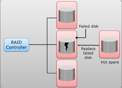
A hot sparing refers to a process that temporarily replaces a failed disk drive with a spare  drive in a RAID array by taking the identity of the failed disk drive. When a new disk drive is added to the system, data from the hot spare is copied to it. The hot spare returns to its idle state, ready to replace the next failed drive. Alternatively, the hot spare replaces the failed disk drive permanently. This means that it is no longer a hot spare is available now, and a new hot spare must be configured on the storage system. 

A hot spare should be large enough to accommodate data from a failed drive. Some systems implement multiple hot spares to improve data availability. 

Hotspare


A hot spare can be configured as automatic or user initiated, which specifies how it will be  used in the event of disk failure. In an automatic configuration, when the recoverable error rates for a disk exceed a predetermined threshold, the disk subsystem tries to copy data from the failing disk to the hot spare disk automatically. If this task is completed before the  damaged disk fails, the subsystem switches to the hot spare and marks the failing disk as unusable. Otherwise, it uses parity or the mirrored disk to recover the data. In the case of a user-initiated configuration, the administrator has control of the rebuild process. For example, the rebuild could occur overnight to prevent any degradation of system performance. However, the system is at risk of data loss if another disk failure occurs.

Some RAID arrays contain a spare drive that is referred to as a hot-spare or an online
spare. This hot-spare operates in standby mode usually powered on but not in use during
normal operating circumstances, but it is automatically brought into action, by the
RAID controller, in the event of a failed drive.

The major use of hot spares is to enable RAID sets to start rebuilding automatically as soon as possible. The process of rebuilding to a hot-spare drive is often referred as sparing out. Some modern storage arrays have physical hot-spare drives but they reserve a small amount of space on each drive in the array and set this space aside to be used in the even of drive failures, this is referred as distributed sparing.

With the hot spare, one of the following methods of data recovery is performed depending on the RAID implementation
  • If parity RAID is used, the data is rebuilt onto the hot spare from the parity and the data on the surviving disk drives in the RAID set.
  • If mirroring is used, the data from the surviving mirror is used to copy the data onto the hot spare.
Drive copy rebuilds are computationally simple compared to parity rebuilds, they are faster than having to reconstruct from parity. RAID 1 mirror sets always recover with a drive copy but parity based RAID levels such as RAID 5 and RAID 6 usually have to recover data through parity rebuild.

Previous: 3.7 Overview of RAID 6 and its use cases

                                                                                            Next: 3.9 The next generation RAID techniques
3.7 Overview of RAID 6 and its use cases

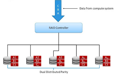
RAID 6 works in the same way as RAID 5, except that RAID 6 includes a second parity element to enable survival if two disk failures occur in a RAID set. Therefore, a RAID 6 implementation requires at least four disks. 


RAID 6 distributes the parity across all the disks. The write penalty in RAID 6 is more than that in RAID 5; therefore, RAID 5 writes perform better than RAID 6. The rebuild operation in RAID 6 may take longer than that in RAID 5 due to the presence of two parity sets. RAID 6 is based on polynomial erasure code technique which are generally used in future RAID techniques, data protection and in cloud based architectures.

                RAID 6 Overview

The parity in RAID 6 is distributed across all members of the RAID set. RAID 5 reserves the equivalent of one drives worth of blocks for parity whereas RAID 6 reserves two drives worth of block for two discrete sets of parity. This enables RAID 6 to suffer two failed drives without losing data. This makes RAID 6 an extremely safe RAID level.

RAID 6 is generally considered extremely safe and RAID 6 performs well in high-read situations. It can suffer two drive failures in the set without losing data. This makes it an ideal choice for use with large drives or for use in pools with large numbers of drives. Large drives tend to be slow drives in terms of revolutions per minute (RPM) and therefore take a lot longer to rebuild than smaller, faster drives. For this reason, the window of exposure to a second drive failure while  performing a rebuild is greatly increased. RAID 6 gives an extra safety  by allowing you to suffer a second drive failure without losing data.

The major downside of RAID 6 is performance, especially performance of small-block writes in an environment experiencing a high number of writes. Because RAID 6 doubles the amount of parity per RAID stripe, RAID 6 suffers more severely from the write penalty than RAID 5. The four I/Os per small-block write for a RAID 5 set becomes six I/Os per write for a RAID 6 set. Therefore, RAID 6 is not recommended for small-block-intensive I/O requirements, and in the vast majority of cases, it is not used for any heavy write-based workloads.

RAID 6 Use Cases

RAID 6 is a good all-round system that combines efficient storage with excellent security and decent performance. It is preferable over RAID 5 in file and application servers that use many large drives for data storage.

Advantages

  • Like with RAID 5, read data transactions are very fast.
  • If two drives fail, you still have access to all data, even while the failed drives are being replaced. So RAID 6 is more secure than RAID 5.

Disadvantages

  • Write data transactions are slowed down due to the parity that has to be calculated.
  • Drive failures have an effect on throughput, although this is still acceptable.
  • This is complex technology. Rebuilding an array in which one drive failed can take a long time.
Previous: 3.6 Overview of RAID 5 and its use cases

                                                                                                          Next: 3.8 What is Hot Sparing ?

2 August 2016

3.6 Overview of RAID 5 and its use cases

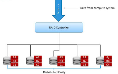
RAID 5 is a versatile RAID implementation. It is similar to RAID 4 because it uses striping. The drives (strips) are also independently accessible. The difference between RAID 4 and RAID 5 is the parity location. In RAID 4, parity is written to a dedicated drive, creating a write bottleneck for the parity disk. In RAID 5, parity is distributed across all disks to overcome the write bottleneck of a dedicated parity disk. 
 
                RAID 5 OVerview


RAID 5 is probably the most commonly deployed RAID level but RAID 6 is considered as best practice for all drives that are 1 TB or larger. RAID 5 is known technically as block-level striping with distributed parity. 

Block level is not bit or byte level. Block size is arbitrary and maps to the chunk size. Whereas distributed parity tells us that there is no single drive in the RAID set designated as a parity drive. Instead, parity is spread over all the drives in the RAID set.

Even though there is no dedicated parity drive in a RAID 5 set, RAID 5 always reserves the equivalent of one disk worth of blocks, across all drives in the RAID set, for parity. When a drive fails in a RAID set, it needs to be rebuild as soon as possible as the RAID will be running in degraded mode. The degraded RAID mode will decrease the RAID performance and its ability to sustain drive failure will be degraded. IF hot-spare is available, the RAID controller can immediately start rebuilding the set by performing OR (XOR) operations against the surviving data in the set. The XOR operation effectively tells the RAID controller what was on the failed drive, enabling the hot-spare drive to be populated with what was on the failed drive. 

RAID 5 Use Cases:

RAID 5 is a good all-round system that combines efficient storage with excellent security and decent performance. It is ideal for file and application servers that have a limited number of data drives.

Advantages

  • Read data transactions are very fast while write data transactions are somewhat slower (due to the parity that has to be calculated).
  • If a drive fails, you still have access to all data, even while the failed drive is being replaced and the storage controller rebuilds the data on the new drive.

Disadvantages

  • Drive failures have an effect on throughput, although this is still acceptable.
  • This is complex technology. If one of the disks in an array using 4TB disks fails and is replaced, restoring the data (the rebuild time) may take a day or longer, depending on the load on the array and the speed of the controller. If another disk goes bad during that time, data is lost forever.

                                                                                           Next: 3.7 Overview of RAID 6 and its use cases

3.5 Overview of RAID 10 and its use cases

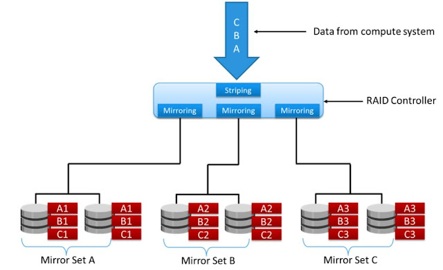
RAID 1+0 is also known as RAID 10 (Ten) or RAID 1/0. RAID 1+0 is also called striped mirror. It is a hybrid of RAID 1 (mirror sets) and RAID 0 (stripe sets). The objective of this RAID type is to combine both striping and mirroring techniques to get both the protection and performance of RAID 0 and RAID 1.


The basic concept of RAID 1+0 is a mirrored pair, which means that data is first mirrored and then both copies of the data are striped across multiple disk drive pairs in a RAID set.   


RAID 10


When replacing a failed drive, only the mirror is rebuilt. In other words, the storage system controller uses the surviving drive in the mirrored pair for data recovery and continuous operation. 

Data from the surviving disk is copied to the replacement disk. Most data centers require data redundancy and performance from their RAID arrays. RAID 1+0 combines the performance benefits of RAID 0 with the redundancy benefits of RAID 1. It uses mirroring and striping techniques and combines their benefits. This RAID type requires an even number of disks and the minimum is four.

RAID 10 and RAID 01 are not the same, and people often get confused the two . You
always want RAID 10 rather than RAID 01. The technical difference is that RAID 01 first
creates two stripe sets and then creates a mirror between them. The major concern with
RAID 01 is that it is more prone to data loss than RAID 10.

RAID 10 Use Cases

Choose RAID 10 if the capacity overhead can be affordable which comes with RAID 1, then RAID 10 potentially offers the best mix of performance and protection available from the traditional levels. 

Advantages

If something goes wrong with one of the disks in a RAID 10 configuration, the rebuild time is very fast since all that is needed is copying all the data from the surviving mirror to a new drive. This can take as little as 30 minutes for drives of  1 TB.

Disadvantages

Half of the storage capacity goes to mirroring, so compared to large RAID 5  or RAID 6 arrays, this is an expensive way to have redundancy.

Previous: 3.4 Overview of RAID 1 and its use cases

                                                                                                  Next: 3.6 Overview of RAID 5 and its use cases

1 August 2016

3.4 Overview of RAID 1 and its use cases

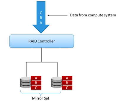
RAID 1 uses the mirroring technique. In this RAID configuration, data is mirrored to provide fault tolerance. A RAID 1 set consists of two disk drives and every write is written to both disks.  These two disks are often referred as mirrored pair and the mirroring is transparent to the compute system. 

When a write request comes to the RAID controller, it is written to both disks in the mirrored pair. Both the disks in this RAID type will always be in sync with each other. For some reason if data is not in sync in the two drives, then the RAID is referred as degraded. It means there is a degraded redundancy and degraded performance. If either of the drives in the RAID set fails, the other can be used to service both reads and writes. If both fail, the data in the RAID set will be lost.

RAID 1

RAID 1 is considered as a high performance and safe RAID level because the act of mirroring writes is computationally lightweight when compared with parity based RAID. It is also considered as safe because the rebuild times can be relatively fast as the full copy of the data still exists on the surviving disk drive and the RAID set can be rebuild through the fast copy rather than a slower parity rebuild.

During disk failure, the impact on data recovery in RAID 1 is the least among all RAID implementations. This is because the RAID controller uses the mirror drive for data recovery. When a drive fails in a RAID 1 set, the set is marked as degraded but all read/write operations will continue and you might see some impact on read performance. Once the failed drive is replaced with a new drive, the RAID set will be rebuilt by the drive copy operation and all the contents of the surviving drive are copied to the new drive and RAID set will be in full redundancy mode.

The only disadvantage of this RAID type is it is expensive. Since it requires double of the storage capacity for mirroring the data, it is required to buy the extra storage space for getting redundancy and protection.

RAID 1 Use Cases

RAID-1 is ideal for mission critical storage, for instance for accounting systems. It is also suitable for small servers in which only two data drives will be used. Choose RAID 1 if
  • Applications require high availability and cost is not a constraint.
  • High write performance is needed as there is no write penalty for small random writes when compared with RAID 5 and RAID 6.
  • High read performance is required as the data read operation can be satisfied from either of the drives in the mirrored pair. This will provide higher IOPS from both the drives which is not available in other RAID types.

Advantages

  • RAID 1 offers excellent read speed and a write-speed that is comparable to that of a single drive.
  • In case a drive fails, data do not have to be rebuild, they just have to be copied to the replacement drive.
  • RAID 1 is a very simple technology.

Disadvantages

  • The main disadvantage is that the effective storage capacity is only half of the total drive capacity because all data get written twice.
  • Software RAID 1 solutions do not always allow a hot swap of a failed drive. That means the failed drive can only be replaced after powering down the computer it is attached to. For servers that are used simultaneously by many people, this may not be acceptable. Such systems typically use hardware controllers that do support hot swapping.

Previous: 3.3 Overview of RAID 0 and its use cases

                                                                                             Next: 3.5 Overview of RAID 10 and its use cases

31 July 2016

3.3 Overview of RAID 0 and its use cases

RAID 0 does not offer data redundancy as it does not use parity or mirroring techniques. RAID 0 uses striping technique to store the data without using the parity. The striping means that data is spread over all the drives in the RAID set, yielding parallelism. 

RAID 0 configuration uses data striping techniques, where data is striped across all the disks within a RAID set. Therefore it utilizes the full storage capacity of a RAID set. To read data, all the strips are gathered by the controller. When the number of drives in the RAID set increases, the performance improves because more data can be read or written simultaneously. 

RAID 0


RAID 0 is a good option for applications that need high I/O throughput. However, if these applications require high availability during drive failures, RAID 0 does not provide data protection and availability. When any drive in the RAID 0 fails, all the data in that failed drive is lost and it is unrecoverable unless you have other types of protection (backup or replication).

There is no RAID overhead with RAID 0, as no capacity is utilized for mirroring or parity. There is also no performance overhead, as there are no parity calculations to perform.


RAID 0 Use Cases

Choose RAID 0 if 
  • The data is 100 percent scratch, losing it is not a problem, and you need as much capacity out of your drives as possible.
  • As long as there is some other form of data protection such as network RAID or a replica copy that can be used in the event that you lose data in your RAID 0 set.
  • If you want to create a striped logical volume on top of volumes that are already RAID protected. such as creating volumes on already RAID protected LVM in Linux servers.

Advantages

  • RAID 0 offers great performance, both in read and write operations. There is no overhead caused by parity controls.
  • All storage capacity is used, there is no overhead.
  • The technology is easy to implement.

Disadvantages

RAID 0 is not fault-tolerant. If one drive fails, all data in the RAID 0 array are lost. It should not be used for mission-critical systems.


Previous: 3.2 Types of RAID Levels

                                                                                              Next: 3.4 Overview of RAID 1 and its use cases

3.2 Types of RAID Levels

There are different types of RAID levels which we can use in the storage systems. The RAID level selection depends on the parameters such as application performance, data availability requirements, and cost. These RAID levels are defined on the basis of striping, mirroring, and parity techniques. Some RAID levels use a single technique, whereas others use a combination of techniques. Commonly used RAID levels are
  • RAID 0 - Striped set with no fault tolerance
  • RAID 1 - Disk Mirroring
  • RAID 1 + 0 - Nested RAID
  • RAID 3 - Striped set with parallel access and dedicated parity
  • RAID 5 - Striped set with independent disk access and distributed parity
  • RAID 6 - Striped set with independent disk access and dual distributed parity

Comparing RAID Levels

When choosing a RAID type, it is imperative to consider its impact on disk performance and application IOPS. In both mirrored and parity RAID configurations, every write operation translates into more I/O overhead for the disks, which is referred to as a write penalty. The commonly used RAID types during these days are

RAID 1 offers good performance but comes with a 50 percent RAID capacity overhead. It’s a great choice for small-block random workloads and does not suffer from the write penalty.

RAID 5 is block-level interleaved parity, whereby a single parity block per stripe is rotated among all drives in the RAID set. RAID 5 can tolerate a single drive failure and suffers from the write penalty when performing small-block writes.

RAID 6 is block-level interleaved parity, whereby two discrete parity blocks per stripe are rotated among all drives in the RAID set. RAID 6 can tolerate a two-drive failure and suffers from the write penalty when performing small-block writes.

RAID Comparison


In a RAID 1 implementation, every write operation must be performed on two disks configured as a mirrored pair, whereas in a RAID 5 implementation, a write operation may manifest as four I/O operations. When performing I/Os to a disk configured with RAID 5, the controller has to read, recalculate, and write a parity segment for every data write operation.

For example a single write operation on RAID 5 that contains a group of five disks. The parity (P) at the controller is calculated as follows

Cp = C1 + C2 + C3 + C4 (XOR operations)

Whenever the controller performs a write I/O, parity must be computed by reading the old parity (Cp old) and the old data (C4 old) from the disk, which means two read I/Os. Then, the new parity (Cp new) is computed as follows

Cp new = Cp old – C4 old + C4 new (XOR operations)

After computing the new parity, the controller completes the write I/O by writing the new data and the new parity onto the disks, amounting to two write I/Os. Therefore, the controller performs two disk reads and two disk writes for every write operation, and the write penalty is 4.

But in RAID 6, which maintains dual parity, a disk write requires three read operations: two parity and one data. After calculating both the new parities, the controller performs three write operations: two parity and an I/O. Therefore, in a RAID 6 implementation, the controller performs six I/O operations for each write I/O, and the write penalty is 6.

The detailed description of the above RAID levels and their use cases are explained in the next posts.


Less Commonly used RAID Levels

Some RAID levels are not commonly used in today's data centres either due to complexity or cost issues. The other types of RAID levels which are not or rarely in use are

RAID 2 
RAID 2 is bit level striping and it is the only RAID that can recover from single-bit errors.

RAID 3
RAID 3 performs parity at the byte level and uses a dedicated parity drive. RAID 3 stripes data for performance and uses parity for fault tolerance. Parity information is stored on a dedicated parity drive so that the data can be reconstructed if a drive fails in a RAID set

RAID 4

RAID 4 is similar to RAID 5. It performs block-level striping but has a dedicated parity drive. The common issues with using dedicated parity drives is that the parity drive can become a bottleneck for write performance. Every single block update on each row requires updating the parity on the dedicated parity drive which can cause the parity drive to become a bottleneck. One advantage of this type of RAID is that it can be easily expanded by adding more disks to the set by only rebuilding the parity drive. 


Previous: 3.1 Redundant Array of Independent Disks (RAID) Overview

                                                                                                                             Next: 3.3 Overview of RAID 0 and its use cases

28 July 2016

3.1 Redundant Array of Independent Disks (RAID) Overview

One of the main feature why the storage systems became intelligent is by using the technique called RAID. A group of disk drives which combinely referred as an disk array are very expensive, have single point of failure and have limited IOPS. Most large data centers experience multiple disk drive failures each day due to increase in capacity and decrease in performance. To overcome these limitations, 25 years ago a technique called RAID is introduced for the smooth uninterrupted running of the data centers. A properly configured RAID will protect the data from failed disk drives and improve I/O performance by parallelizing I/O across multiple drives.


What is a RAID ?

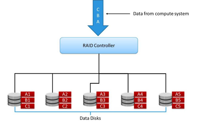
RAID is abbreviated as Redundant Array of inexpensive/independent Disks (RAID) which is a technique in which multiple disk drives are combined into a logical unit called a RAID set and data is written in blocks across the disks in the RAID set. RAID protects against data loss when a drive fails, through the use of redundant drives and parity. RAID also helps in improving the storage system performance as read and write operations are served simultaneously from multiple disk drives.


RAID
RAID is typically implemented by using a specialised hardware controller present either on the compute system or on the storage system. The key functions of a RAID controller are management and control of drive aggregations, translation of I/O requests between logical and physical drives, and data regeneration in the event of drive failures.

A RAID array is an enclosure that contains a number of disk drives and supporting hardware to implement RAID. A subset of disks within a RAID array can be grouped to form logical associations called logical arrays, also known as a RAID set or a RAID group.

There are two methods of RAID implementation, hardware and software. Both have their advantages and disadvantages.

Software RAID

Software RAID uses compute system-based software to provide RAID functions and is implemented at the operating-system level. Software RAID implementations offer cost and simplicity benefits when compared with hardware RAID. However, they have the following limitations
  • Performance: Software RAID affects the overall system performance. This is due to additional CPU cycles required to perform RAID calculations.
  • Supported features: Software RAID does not support all RAID levels.
  • Operating system compatibility: Software RAID is tied to the operating system; hence, upgrades to software RAID or to the operating system should be validated for compatibility. This leads to inflexibility in the data-processing environment.
Hardware RAID

In hardware RAID implementations, a specialised hardware controller is implemented either on the server or on the storage system. Controller card RAID is a server-based hardware RAID implementation in which a specialised RAID controller is installed in the server, and disk drives are connected to it. Manufacturers also integrate RAID controllers on motherboards. A server-based RAID controller is not an efficient solution in a data center environment with a large number of servers.

The external RAID controller is a storage system-based hardware RAID. It acts as an interface between the servers and the disks. It presents storage volumes to the servers, and the servers manages these volumes as physical drives. The key functions of the RAID controllers are as follows
  • Management and control of disk aggregations
  • Translation of I/O requests between logical disks and physical disks
  • Data regeneration in the event of disk failures

Hardware RAID  can offer increased performance, faster rebuilds, and hot-spares, and can protect OS boot volumes. However, software RAID tends to be more flexible and cheaper.


RAID Techniques

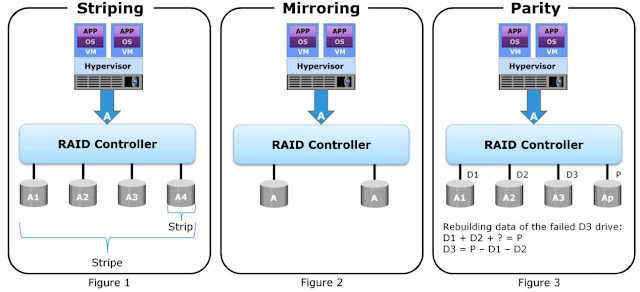
The three different RAID techniques that form the basis for defining various RAID levels are striping, mirroring, and parity. These techniques determine the data availability and performance of a RAID set as well as the relative cost of deploying a RAID level.

RAID Techniques


Striping: Striping is a technique of spreading data across multiple drives (more than one) in order to use the drives in parallel. All the read-write heads work simultaneously, allowing more data to be processed in a shorter time and increasing performance, compared to reading and writing from a single disk. 

Mirroring: Mirroring is a technique whereby the same data is stored on two different disk drives, yielding two copies of the data. If one disk drive failure occurs, the data remains intact on the surviving disk drive and the controller continues to service the compute system’s data requests from the surviving disk of a mirrored pair. When the failed disk is replaced with a new disk, the controller copies the data from the surviving disk of the mirrored pair. This activity is transparent to the server. 

In addition to providing complete data redundancy, mirroring enables fast recovery from disk failure. However, disk mirroring provides only data protection and is not a substitute for data backup. Mirroring constantly captures changes in the data, whereas a backup captures point-in-time images of the data. Mirroring involves duplication of data i.e the amount of storage capacity needed is twice the amount of data being stored. Therefore, mirroring is considered expensive and is preferred for mission-critical applications that cannot afford the risk of any data loss. 

Mirroring improves read performance because read requests can be serviced by both disks. However, write performance is slightly lower than that in a single disk because each write request manifests as two writes on the disk drives. Mirroring does not deliver the same levels of write performance as a striped RAID.

Parity: Parity is a method to protect striped data from disk drive failure without the cost of mirroring. An additional disk drive is added to hold parity, a mathematical construct that allows re-creation of the missing data. Parity is a redundancy technique that ensures protection of data without maintaining a full set of duplicate data. Calculation of parity is a function of the RAID controller. Parity information can be stored on separate, dedicated disk drives, or distributed across all the drives in a RAID set. 

Now, if one of the data disks fails, the missing value can be calculated by subtracting the sum of the rest of the elements from the parity value, parity calculation is a bit wise XOR operation.

Compared to mirroring, parity implementation considerably reduces the cost associated with data protection. Consider an example of a parity RAID configuration with four disks where three disks hold data, and the fourth holds the parity information. In this example, parity requires only 33 percent extra disk space compared to mirroring, which requires 100 percent extra disk space. However, there are some disadvantages of using parity. Parity information is generated from data on the data disk. Therefore, parity is recalculated every time there is a change in data. This recalculation is time-consuming and affects the performance of the RAID array.

As a best practice, it is highly recommend to create the RAID set from drives of the same type, speed, and capacity to ensure maximum usable capacity, reliability, and consistency in performance. For example, if drives of different capacities are mixed in a RAID set, the capacity of the smallest drive is used from each drive in the set to make up the RAID set’s overall capacity. The remaining capacity of the larger drives remains unused. Likewise, mixing higher speed drives with lower speed drives lowers the overall performance of the RAID set.


                                                                                                         Next: 3.2 Types of RAID Levels

2.7 Accessing data from the Intelligent Storage Systems

Data is stored and accessed by applications using the underlying storage infrastructure. The key components of this infrastructure are the OS (or file system), connectivity, and storage. The server controller card accesses the storage devices using predefined protocols, such as IDE/ATA, SCSI, or Fibre Channel (FC) as discussed in earlier posts.

IDE/ATA and SCSI are popularly used in small and personal computing environments for accessing internal storage. FC and iSCSI protocols are used for accessing data from an external storage device (or subsystems). External storage devices can be connected to the servers directly or through the storage network. When the storage is connected directly to the servers, it is referred as Direct-Attached Storage (DAS). 

By using the above SAN features and protocols data which is stored in the storage systems can be accessed by various methods. The overview of these methods are discussed below. Detail description will be in the next posts.

Data Access Methods from Storage Systems

Data can be accessed over a storage network in one of the following ways
  • Block Level
  • File Level
  • Object Level
In general, the application requests data from the file system or operating system by specifying the filename and location. The file system has two components
  • User component
  • Storage component. 
The user component of the file system performs functions such as hierarchy management, naming, and user access control. The storage component maps the files to the physical location on the storage device. 

The file system maps the file attributes to the logical block address of the data and sends the request to the storage device. The storage device converts the logical block address (LBA) to a cylinder-head-sector (CHS) address and fetches the data.

Depending on the type of the data access method used for a storage system, the controller can either be classified as block-based, file-based, object-based, or unified. An intelligent storage system can have all hard disk drives, all solid state drives, or a combination of both. The different types of data access methods are shown in the below figure.

Data Access Methods


Block Level Access


In a block-level access, the file system is created on a server, and data is accessed on a network at the block level. In this case, raw disks or logical volumes are assigned to the servers for creating the file system.

File Level Access


In a file-level access, the file system is created on a separate file server or at the storage side, and the file-level request is sent over a network. Because data is accessed at the file level, this method has higher overhead, as compared to the data accessed at the block level.

Object Level Access


Object-level access is an intelligent evolution, whereby data is accessed over a network in terms of self-contained objects with a unique object identifier. In this type of access, the file system’s user component resides on the server and the storage component resides on the storage system. This type of data access method is mainly used for offering emerging technologies like cloud and big data.

Previous: 2.6 What are Intelligent Storage Systems ?

                                                                                  Next: 3.1 Redundant Array of Independent Disks (RAID) Overview